SM3000 DELTA ELEKTRONIKA BV
1991, rev. May 2008 OPERATING MAINTENANCE TROUBLE SHOOTING CALIBRATING Page 4 - 3
•
Note: The SM300-10D needs an ex tra par allel di ode on the
output, without this di ode the in ternal di ode will still blow. For
this di ode 2 par alleled BYT261-PIV-400 from ST can be used.
The SM300-10D with op tion P023 has an extra di ode built-in.
8)
REMOTE SHUT DOWN / OVER CUR RENT TRIP
• The Remote ShutDown can be op erated with +5 V or a re lay
contact (see fig. 4 - 10).
• Using the Remote ShutDown in put, an Over Cur rent Trip
could be made (see fig. 4 - 10).
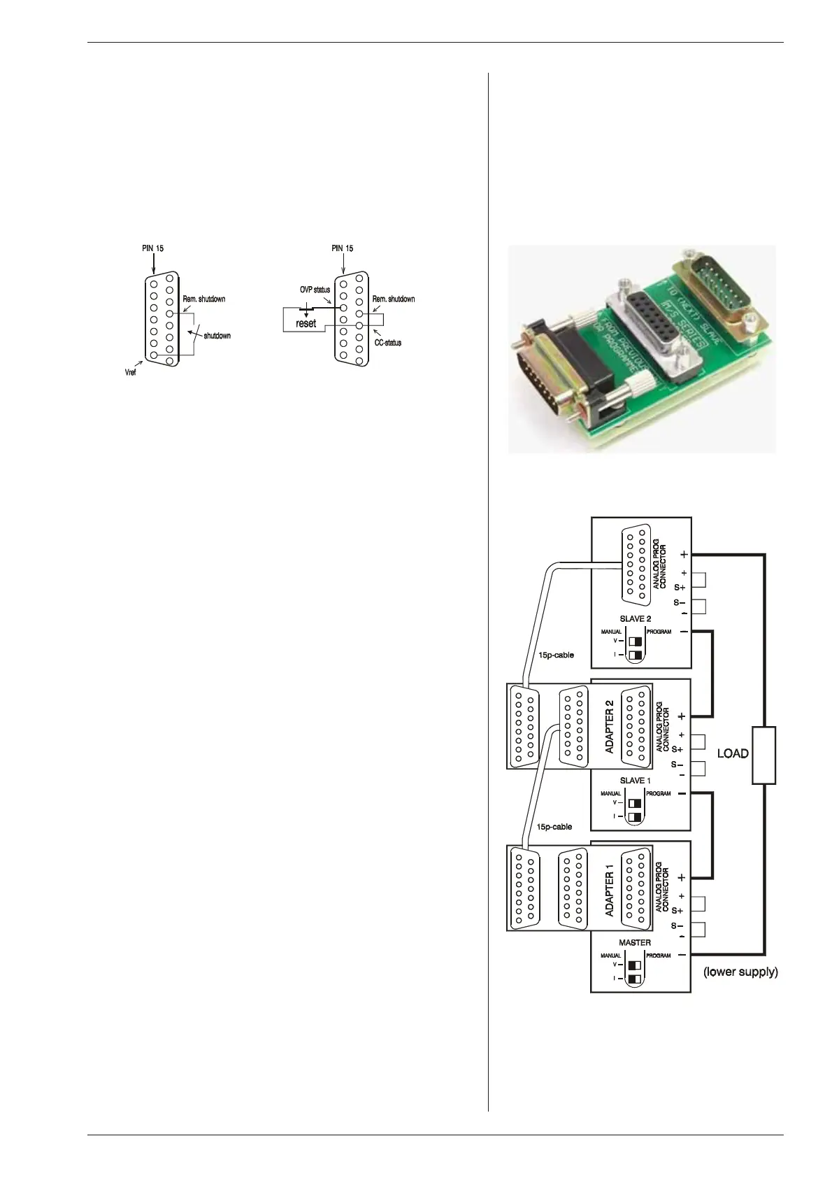
9) MASTER / SLAVE SERIES OP ERATION
• For se ries op er a tion the MAS TER / SLAVE SE RIES ADAP-
TER
(δ-prod uct) must be used (see fig. 4 - 11).
• First, connect output terminals and test sys tem in nor mal se-
ries op eration. Ensure that all (out put) power con nections are
reliable. An in terruption of one of the power leads can cause a
fuse to blow in the unit, see ''trou ble shoot ing''.
• The voltage drop in the con necting leads be tween the units
should be kept < 10 mV.
• Second, switch off all units. Con nect units as shown in fig. 4 -
12. Use standard 15 pole (1:1) shielded ca bles.
• The max. num ber of slaves is only limited by the max. total volt-
age of 600 V.
10)
MASTER / SLAVE PAR AL LEL OP ER A TION
• Note: Master / Slave parallel is not recommended for more
than 4 units, con sult factory for us ing more than 4 power
sup plies in par al lel.
• First con nect output terminals and test sys tem in nor mal par al-
lel op eration. Ensure that all power con nections are reliable. An
interruption of one of the (output) power leads can cause a fuse
to blow in the unit, see “trou ble shoot ing”.
• Second, switch off all units. Plug in prog. connectors with the
con nec tions ac cord ing to fig. 4 - 13 (buss bar to pology). Always
use a shielded ca ble. The shielding must be connected to the
case of the supply.
Disconnect the links be tween the S– and – of the slaves only.
If not re moved the current sharing will not be pro portional.
Both prog. switches of the slaves should be in the po sition PRO-
GRAM.
• The pur pose of the link be tween pin 9 and 11 is to set the volt -
age limit of the slaves at max imum.
• Keep the load close to the master. Keep wir ing be tween mas ter
and slaves short. The voltage drop be tween a unit and the buss
bar should be kept < 10 mV.
• Accidental in terruption of a neg ative load lead of a unit dur ing
operation will cause fuse F600 to blow, see sec tion ‘trouble
shoot ing’.
• The S− and S+ could be connected to the load if de sired, but this
is not recommended be cause of the com plexity.
fig. 4 - 10
Left: Remote ShutDown with switch.
Right: Over Current Trip
fig 4 - 11
The Master / Slave Series Adapter,
supplied by Delta Elektronika
fig. 4 - 12
Master / Slave Series Connection with
two MASTER / SLAVE SERIES ADAPTERS

 Loading...
