DELTA ELEKTRONIKA BV SM3000
Page 3 - 4 DESCRIPTIONS 1991, rev. May 2008
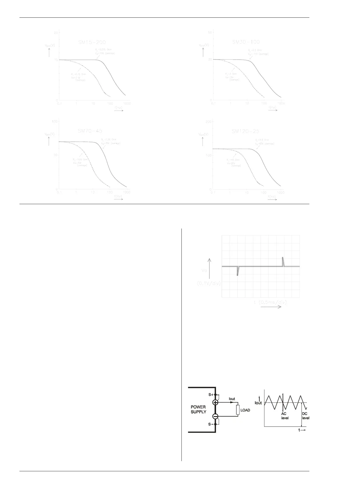
14) PRO GRAMMING BAND WIDTH
For small sig nals the band width is 50 Hz, but for large sig nals
there is a limitation in the maximum am plitude of the out put wave -
form. The out put ca pacitors limit the max. slew rate. Fig ure 3 - 13
shows the maximum peak to peak out put voltage swing as a
function of frequency, with the load as a pa rameter. The higher
the load re sistance the lower the max. am plitude. The mea sure-
ments were car ried out us ing a sine wave. The DC level of the
output is 50 % of the max. out put voltage.
15)
RE COVERY TIME
Fig ure 3 - 14 shows the recovery time for the SM30-100D at
25 °C, set at 30 V output voltage, with a 50 – 100% load step.
16)
NOISE SUP PRESSION (in put / out put)
The in put / output noise sup pression is mea sured with a pulse
generator (a) in se ries with the line in put or (b) be tween in put and
case (earth). The gen erator should produce a high en ergy pulse
of about 300 V. If there is an electrical con nection be tween the
output and the in put through the os cilloscope, you will get a false
reading. The suppression for the SM120-25D is lower, but the
rel a tive dis tur bance on the out put is com pa ra ble to the
SM30-100D.
17)
PUL SATING LOAD
To avoid overheating the out put ca pacitors, the AC component
of the load current should be limited (see fig. 3 - 15).
One method of de creasing the AC current through the output ca -
pac i tor is by us ing a large ex ter nal elec tro lytic ca pac i tor in par al -
lel with the load. Care must be taken so that the ca pacitor in
combination with the lead in ductance will not form a series reso-
nant cir cuit!
When us ing re mote sens ing on a pul sating load (for in stance a
DC-motor), use a ca pacitor in se ries with a re sistor over the load
(see fig. 3 - 16). Like this the AC-component caused by the pul -
sating of the load is fil tered.
With pulsating loads the I-monitor out put should not be used.
fig. 3 - 13
Max. peak to peak out put voltage swing vs frequency
fig. 3 - 14
Re cov ery time SM30-100D
50 - 100 % load step, Vo=30 V
fig. 3 - 15
Pulsating load current

 Loading...
