SM3000 DELTA ELEKTRONIKA BV
1991, rev. May 2008 DESCRIPTIONS Page 3 - 3
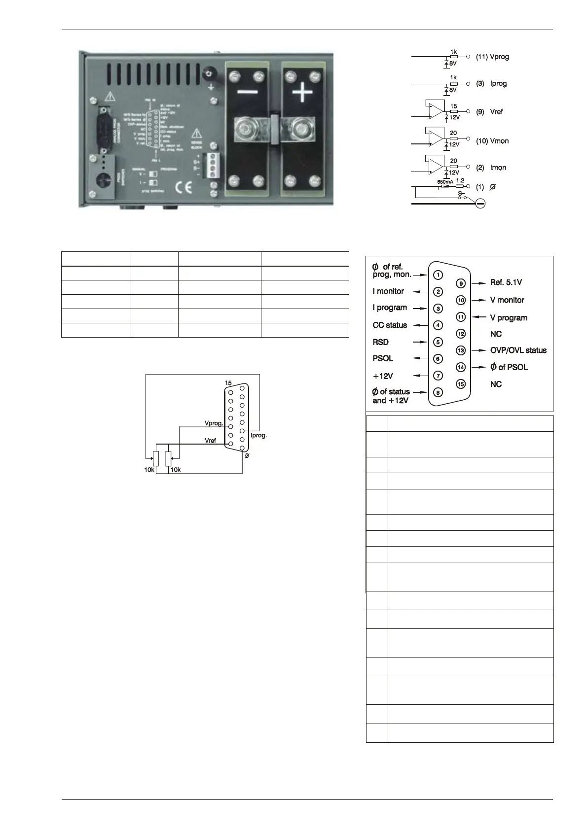
fig. 3 - 9
Lo ca tion of out put ter mi nals and an a log prog. con nector on rear panel
fig. 3 - 10
Buf fered mon i tor out puts (in ter nal cir cuit)
Out put pin Ro Io max
Vref 9 15 Ohm 10 mA
Vmon 10 20 Ohm 10 mA
Imon 2 20 Ohm 10 mA
+12V 7 500 Ohm 25 mA
Ø 1 1.2 Ohm
ta ble 3 - 1
Out puts on pro gram ming con nec tor
11) STATUS OUT PUTS
The status outputs have an open output voltage of 5 V and a short cir -
cuit current of 10 mA. This makes it pos sible to drive di rectly: an
opto-coupler, a TTL gate or a CMOS gate (put leak age re sistor to Ø).
12)
RE MOTE SHUT DOWN
A volt age of +5V on the Re mote Shut Down in put on the programming
connector will switch off the power cir cuit of the unit. In standby mode
the power sup ply con sumes very lit tle power.
It is also pos sible to use a re lay con tact or a switch to shut down the
unit: con nect a switch be tween Vref and Rem. Shut Down (pin 9 and 5).
Note: The Re mote Shut Down will also cause the OVP-led to burn and
the OVP-sta tus will be high.
13)
PRO GRAMMING SPEED
The re sponse time is mea sured with a step wave form at the CV prog.
input. Programming from a low to a high out put voltage is nearly load
independent, but pro gramming down to a low voltage takes more time
on lighter loads. This is caused by the out put ca pacitors, which can
only be dis charged by the load be cause the power sup ply can not sink
cur rent.
When hav ing a sup ply with a fast pro gram ming op tion, the response
is 5 to 25 times faster (see datasheet). When us ing fast pro gramming it
is gen erally not recommended to use remote sensing or se rial / parallel
operation. Con sult factory for ad vice. Also the output rip ple is higher.
fig. 3 - 11
External potmeters
pin de scrip tion
1 Ø, re turn of ref erence, prog. in puts and
mon i tor out puts.
2 current mon itor output (0 - 5V)
3 current pro gramming in put (0 - 5V)
4 CC sta tus output, logic 1 = CC mode
(5 V / 10 mA)
5 Re mote ShutDown
6 PSOL sta tus output (op tional)
7 +12 V output (Ri = 500 Ohm)
8 Ø, re turn of sta tus outputs, +12 V and
re mote ShutDown
9 ref er ence volt age 5.1 V
10 voltage mon itor output (0 - 5V)
11 volt age pro gram ming in put
(0 - 5V)
12 NC
13 OVP sta tus output, logic 1 = OVP mode
(5 V / 10 mA)
14 Ø, re turn of PSOL (op tional)
15 NC
fig. 3 - 12
Con nec tions AN A LOG PROG. CONN.

 Loading...
