SM6000 DELTA ELEKTRONIKA BV
July 2003, rev. May 2008 DESCRIPTIONS Page 3 - 3
The Cur rent Con trol Status or CC-status out put is "1" when the unit is in
CC-mode.
The Power Sink Over Load Sta tus or PSOL-status out put is "1" when the op tional
Power Sink is over loaded or over heated.
The AC-Fail Sta tus or ACF-sta tus out put is "1" in case of Phase Loss or when the
input voltage is be low 340 V.
The DC-Fail Sta tus or DCF-sta tus out put is "1" when the out put voltage is ei ther
5% be low or above the set point.
When the unit is in CC-mode, DCF will al ways be "1", see pre vious para graph 7).
15)
STATUS RE LAY OUT PUTS
The power supply has 2 status re lay out puts, with each a change-over contact.
They are connected to con nector CON D. The pins 1,2,3 are con nected to the
DCF-relay and pins 4,5,6 to the ACF-relay (see fig. 3 - 10).
16)
FUNCTION SWITCHES ON SW1
In the following ta ble the functions of the DIP switches 1-4 of switch SW1 (rear
side) are explained:
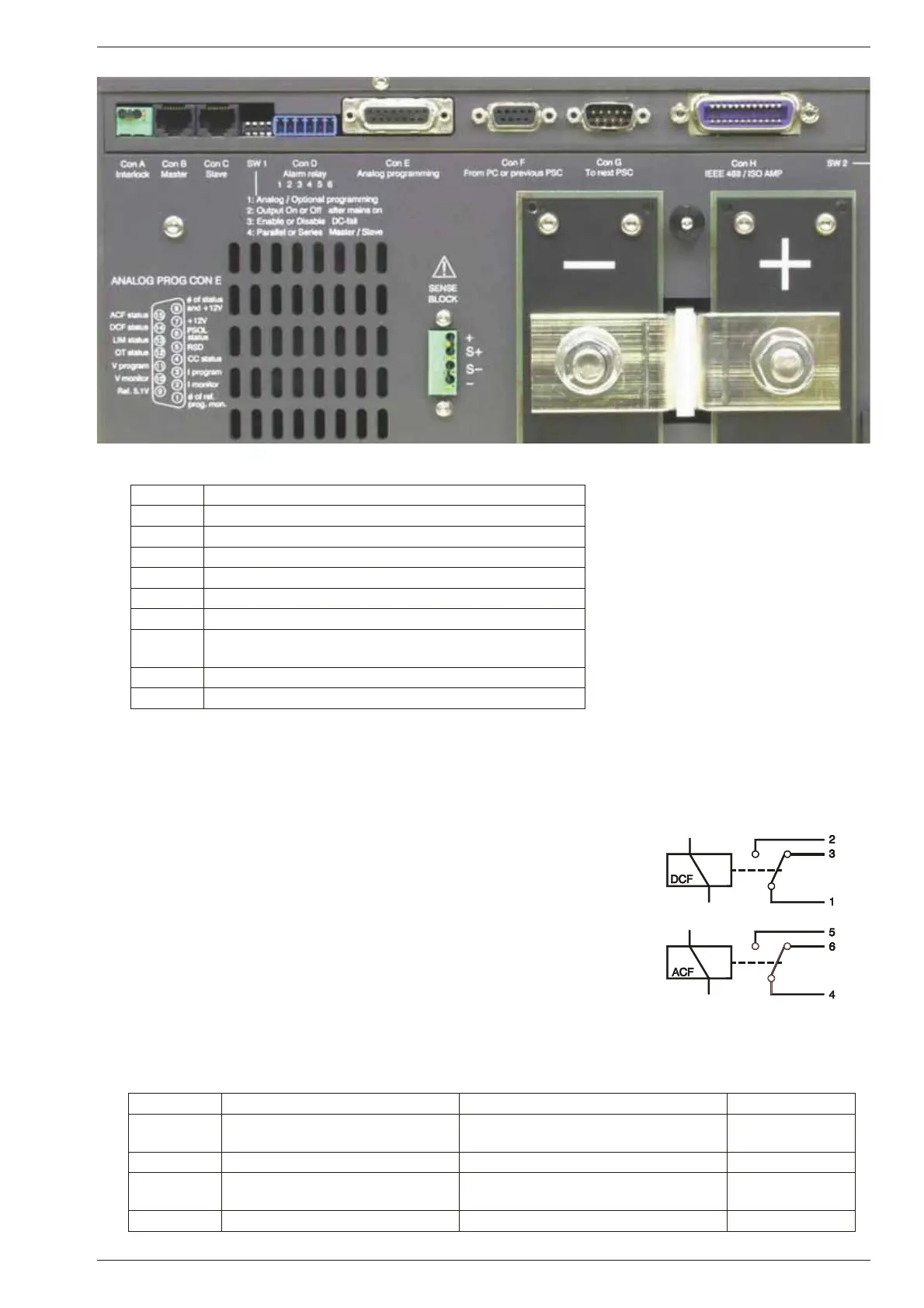
fig. 3 - 8 Location of out put terminals and an alog prog. con nector on rear panel
Switch no. ON po si tion OFF po si tion De fault Set ting
SW 1 - 1 Pro gramming via 15pole con nec-
tor CON E (an alog).
Op tional pro gram ming with e.g.
PSC-232, PSC-488, ISO AMP CARD
ON (up)
SW 1 - 2 ‘Output On’ af ter mains on ‘Output Off’ af ter mains on OFF (down)
SW 1 - 3 DCF LED enabled DCF LED dis abled (DCF sta tus and
DCF re lay are still en abled)
ON (up)
SW 1 - 4 Parallel Mas ter / Slave operation Series Mas ter / Slave operation ON (up)
CON A In ter lock Con nec tor
CON B Master connector for Mas ter / Slave op eration (out put)
CON C Slave con nector for Mas ter / Slave op eration (in put)
CON D Relay Out puts, con tacts 1 - 6
CON E An a log Pro gramming Connector
CON F PSC-232, from PC or pre vious PSC (op tional)
CON G PSC-232, to next PSC (op tional)
CON H PSC-488 (op tional) or
ISO AMP CARD (optional)
SW 1 Var i ous set tings, see para graph 16)
SW 2 Set tings for PSC-488 and PSC-232 (op tional)
fig. 3 - 9 Connectors and switches on the rear panel
fig. 3 - 10
Status relay outputs on CON D.
This sit uation gives the relay
po si tions dur ing fault con di tion.
 Loading...

