SM6000 DELTA ELEKTRONIKA BV
July 2003, rev. May 2008 OPERATING MAINTENANCE TROUBLE SHOOTING CALIBRATING Page 4 - 4
If DIP switch 4 of SW1 is op erated when the unit is
turned on, the out put will shutdown to avoid accidental
dam age.
• The max. num ber of slaves is only limited by the max.
total voltage of 600 V.
12)
MASTER / SLAVE PAR AL LEL OP ER A TION
• Note: Mas ter / Slave par allel is not rec ommended
for more than 3 units, con sult factory for using
more than 3 power sup plies in parallel.
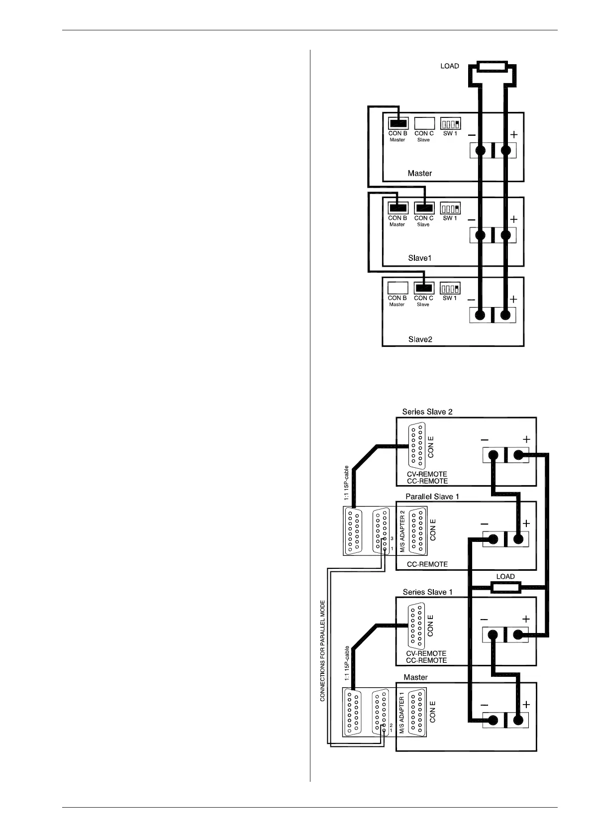
• First con nect output terminals and test sys tem in
nor mal par al lel op eration. Ensure that all power
con nec tions are re li able.
• Second, switch off all units. To con nect the slaves with
the mas ter via CON B and CON C, use standard RJ45
con nec tors ac cord ing to fig. 4 - 11.
On all units put DIP switch 4 of SW1 in po sition ON to
set the units in M/S par allel mode. In this mode the
DCF LED, DCF re lay and DCF sta tus on the slaves are
disabled be cause the slaves are al ways in CC mode.
• After turning the units on again, the slaves will be in
Remote CC mode and the Key lock (see pre vious para -
graph 2) is ac tivated. This is be cause the unit au tomat-
ically de tects the presence of the RJ45 con nec tor in
CON C (if this ca ble is con nected to an other unit).
If the RJ45 con nector is removed from CON C when
the unit is turned on, the out put will shutdown to avoid
ac ci den tal dam age.
If the ca ble is in serted when the unit is turned on, the
output shuts down, the unit changes to Re mote CV /
CC, the Keylock will be activated and the out put will
turn back on.
If DIP switch 4 of SW1 is op erated when the unit is
turned on, the out put will shutdown to avoid accidental
dam age.
• Stack the units to cre ate a min imum dis tance be tween
the units. Keep the load close to the mas ter.
Use cop per strips (pre ferred) or short thick cables to
connect the units. Make sure the strips are mounted
with a min imum length to keep the volt age drop be -
tween a unit and the bus bar be low 10 mV. Also keep
the strips close to each other to have a low in ductance.
Not fol low ing these in struc tions can cause in sta bil ity.
• The S- and S+ could be connected to the load if
desired, but this is not rec ommended be cause of the
com plex ity and pos si ble instability.
13)
PAR AL LEL OP ER A TION OF FAST
PRO GRAMMING VER SIONS:
• Master / Slave op eration is not rec ommended.
• Nor mal par al lel op er a tion can give prob lems, each
combination has to be tested first in com bination with
the load.
14)
MASTER / SLAVE MIXED SERIES /
PAR AL LEL OP ER A TION
• For complex com binations as mixed se ries - parallel,
always use a MASTER / SLAVE SE RIES ADAPTER.
• See fig. 4 - 12 for an ex ample of how to connect 2 units
in se ries in par allel with 2 units in se ries, controlled by 1
mas ter.
• Set the pro gramming mode with the knob Re mote / Lo -
cal on the front panel. The se rial slaves must be in Re-
mote CV- and CC-mode. The par allel slave must be in
Remote CC-mode and the CV-potmeter must be fully
opened.
• Note: A Mas ter / Slave combination can al ways be
programmed, also with the IEEE488/RS232 con trol ler
(PSC-488 / PSC-232
(both δ-prod ucts)).
fig. 4 - 11
Master / Slave parallel connections
fig. 4 - 12
Master / Slave mixed series - parallel connections
 Loading...

