DELTA ELEKTRONIKA BV SM6000
Page 4 - 3 OPERATING MAINTENANCE TROUBLE SHOOTING CALIBRATING July 2003, rev. May 2008
•
Max. 2 V per load lead can be compensated.
Note that the voltage drop in the leads de creases the max.
output voltage rat ing. In fig. 4 - 7 it can be seen that on a 15
V power sup ply only 11 V will be avail able on the load when
2x 2 V com pensation is used.
• In or der to pre vent in terference it is ad visable to twist the
sense leads. To min imize the inductance in the load leads
keep the leads close to each other. The in ductance of the
loads leads could give a prob lem with pul sating loads. In
this case a large elec trolytic ca pacitor (Cd) in se ries with a
damping re sistor (Rd) both in parallel with the load will help
(see fig. 4 - 6). Check that the ca pacitor Cd in combination
with the load leads and re sistor Rd forms a well damped cir -
cuit.
• Since the volt me ter is in ternally con nected to the sens ing
ter mi nals, it will au to mat i cally in di cate the voltage on the
load. Note that the voltage mea sured on the load will be
lower than on the out put terminals.
• The Over Volt age Limit measures the volt age on the out put
ter mi nals, so the OVL set ting should be in creased by the
total voltage drop in the load leads.
9)
BAT TERY CHARGER
• The CV / CC reg ulated power supplies are ideal battery
chargers. Once the output is set at the correct voltage the
battery will charge con stantly with out over charging.
This can be useful for emer gency power systems.
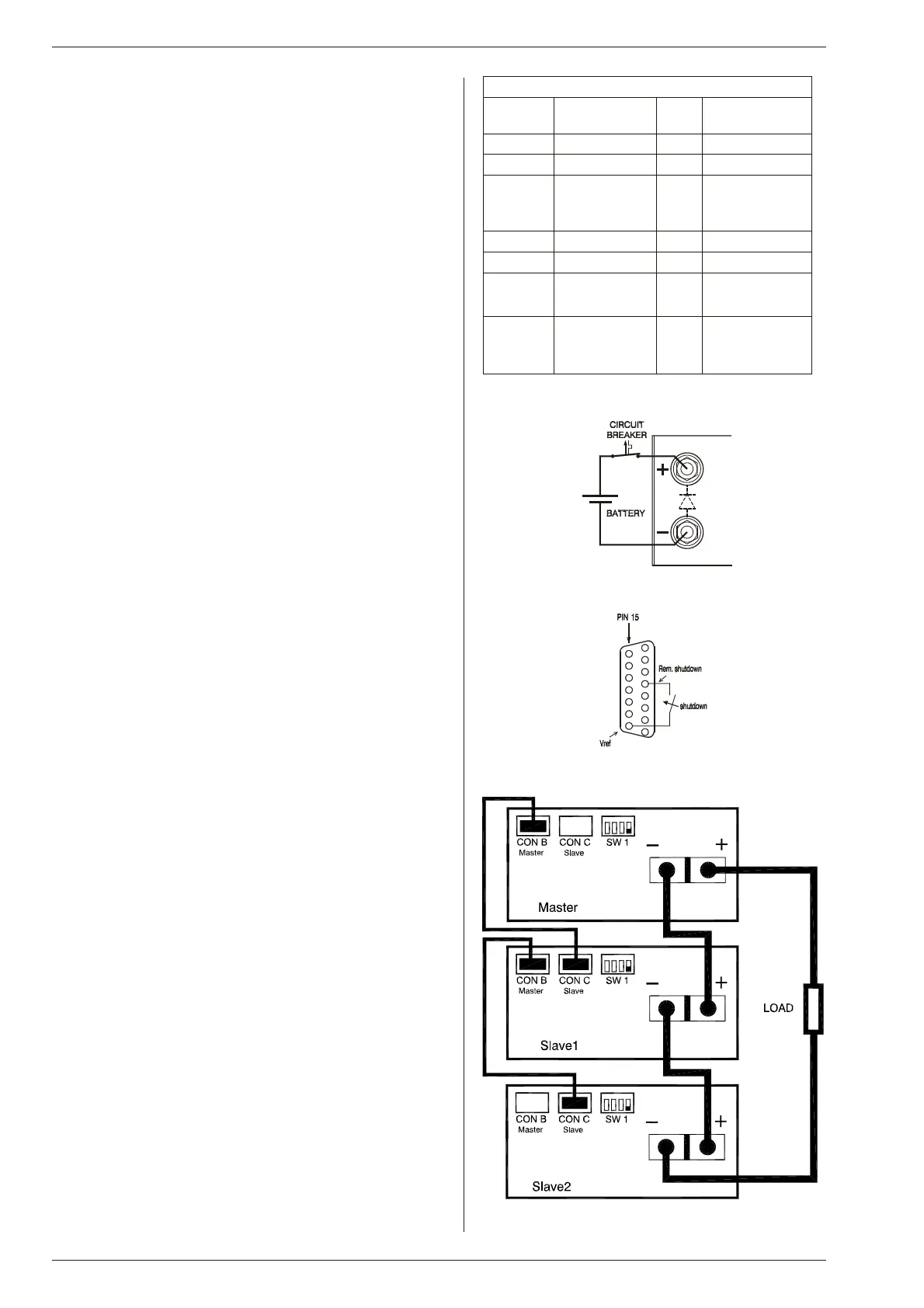
• Pro tec tive mea sures
Use a CIR CUIT BREAKER in se ries in or der to pro tect the
power sup ply from ac ci den tal re verse con nec tion (see
fig. 4 - 8).The cir cuit breaker should have a DC voltage rat -
ing twice the bat tery voltage. Use the very fast type (Z), a
type meant for pro tecting semi conductors (see ta ble 4 - 2).
The unit has a re verse di ode in par allel with the out put, this
diode and the wir ing can not with stand the thou sands of
amperes sup plied by a wrongly connected battery.
10)
RE MOTE SHUTDOWN
• The Re mote ShutDown can be op erated on CON E by a
voltage of +4 V...+12 V or by a re lay con tact be tween Vref
and Re mote Shut Down (pin 9 and 5) (see fig. 4 - 9).
• When the unit is pro grammed with an op tional PSC, a
software com mand can be used for Re mote Shutdown.
• In the Re mote ShutDown con di tion, the RSD LED will light.
The DCF LED, DCF sta tus and the DCF re lay will be off.
Important: If the link from the Interlock con nector (CON A)
has been re moved, the RSD LED will be on, but in this
con di tion also the DCF LED, the DCF sta tus and the DCF
relay will be on.
11)
MASTER / SLAVE SERIES OP ERATION
• Connect output terminals and test sys tem in nor mal
se ries op eration. Ensure that all (out put) power con nec-
tions are reliable.
• The voltage drop in the con necting leads be tween the units
should be kept < 10 mV.
• Switch off all units. Con nect units as shown in fig. 4 - 10.
To con nect the slaves with the mas ter via CON B and CON
C, use standard UTP cables (RJ45).
On all units put DIP switch 4 of SW1 in po sition OFF to set
the units in M/S series mode.
• After turning the units on again, the slaves will be in Re mote
CV mode and the Keylock (see pre vious paragraph 2) is
ac ti vated. This is be cause the unit au to mat i cally de tects
the pres ence of the RJ45 con nec tor in CON C (if this ca ble
is con nected to an other unit).
If the RJ45 con nector is removed from CON C when the
unit is turned on, the out put will shutdown to avoid
ac ci den tal dam age.
If the ca ble is in serted when the unit is turned on, the out put
shuts down, the unit changes to Re mote CV / CC, the Key-
lock will be activated and the out put will turn back on.
Suggested circuit breakers for pro tection power sup ply
Model Type num ber
circuit breaker
Brand Re marks
SM15-400
2x HTI102 B 100 GE 4 poles par allel
SM30-200 HTI102 B 100 GE 2 poles par allel
SM45-140 HTI102 B 100 GE
2 poles par allel
ex tra par al lel di ode
on out put needed
= OP TION 151
SM60-100 HTI101 B 100 GE
SM70-90 HTI101 B 100 GE
SM120-50 S281 UC-Z 50 ABB
ex tra par al lel di ode
on out put needed
= OP TION 152
SM300-20 S282 UC-Z 20 ABB
2 poles in series
ex tra par al lel di odes
on out put needed
= OP TION 153
ta ble 4 - 2
Cir cuit break ers for pro tec tion.
fig. 4 - 8
Charging battery with a circuit breaker in se ries
fig. 4 - 9
Re mote ShutDown with switch
fig. 4 - 10
Master / Slave se ries con nection
 Loading...