DELTA ELEKTRONIKA BV SM6000
Page 3 - 2 DESCRIPTIONS July 2003, rev. May 2008
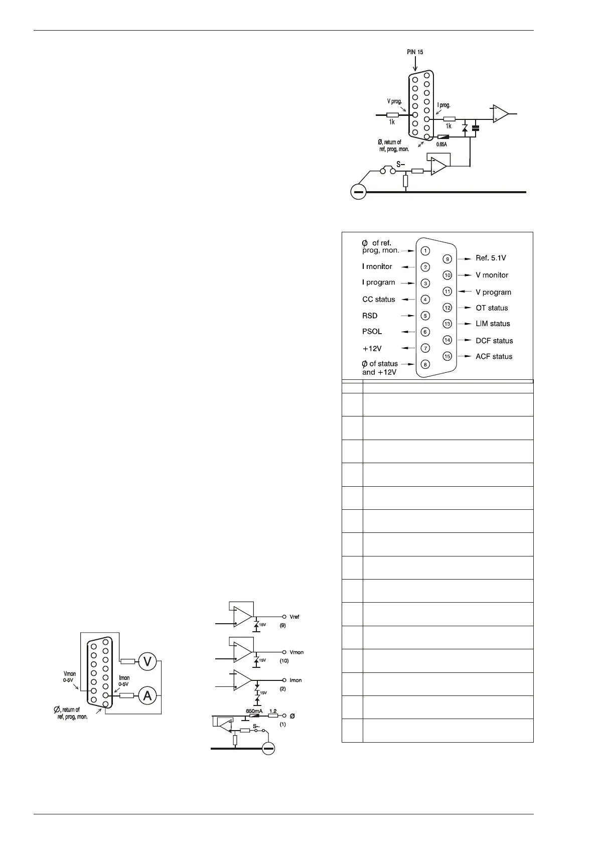
fig. 3 - 4
Pro gram ming in puts (in ter nal cir cuit)
9) AN A LOG PRO GRAMMING
The out put voltage and cur rent can be programmed by an ex ternal an alog
voltage. This pro gramming is very ac curate and lin ear. The lev els are all
standardized on 5 V.
The in puts have a protection circuit formed by a series re sistor and a
par al lel zener (see fig. 3 - 4). The ca pacitor limits the speed to a safe
value. Note that the an alog in puts (and outputs) are not floating, but the
common is connected to the negative output terminal. Wrong con -
nec tion of Ø can cause earth loops which can trip the fuse. After re moving
the fault, the fuse will re set (PTC-fuse). For iso lated pro gramming see
next para graph 10).
10)
ISO LATED AN A LOG PRO GRAMMING
To pre vent earth loops which can cause pro gramming er rors, use an iso -
lated pro gramming source. If this is not pos sible, use the op tional ISO
AMP CARD
(δ-prod uct) which can be built in side the unit.
With the ISO AMP CARD earth loops be tween the unit and the pro gram-
ming source are prevented.
11)
Ethernet / IEEE488 / RS232 PRO GRAMMING
The Delta Elektronika PSC-ETH, PSC-488 and the PSC-232 con trol lers
can be built in side the unit.
Voltage and cur rent can easily be pro grammed and read back. Also all
the status outputs can be read by the computer.
12)
MON I TORING OUT PUTS
The mon itor outputs give a voltage 0 - 5 V pro portional to the out put cur -
rent or voltage. The output cur rent can easily be mea sured us ing the
I-mon i tor (see fig. 3 - 6). The mon itor outputs are buffered with op-amp’s
and pro tected with se ries re sistors and parallel zeners (see fig. 3 - 7). The
table in fig. 3 - 5 shows the impedance lev els of the mon itoring out puts.
For us ing Imon on a pul sating load, see paragraph 20) of this chap ter.
13)
+12 V ON PRO GRAMMING CON NECTOR
The +12 V on the pro gramming con nector can be used to sup ply ex ternal
circuits. The out put is current limited, but should not be overloaded. The
fuse F27_3 on P598 could blow. The fuse F27_3 also pro tects the in ternal
circuit, in case an ex ternal high volt age is ap plied by ac cident. Note: this
fuse is a special 600 V type, al ways re place with the same type.
14)
STATUS OUT PUTS
All the status outputs are logic out puts. Logic "0" means the out put is 0 V,
logic "1" means the out put is 5 V (Ro = 500 Ohm). This makes it pos sible
to drive directly: an opto-coupler, a TTL gate or a CMOS gate.
The Limit Sta tus or LIM-status is "1" in case the out put voltage or cur rent
reaches the limit setting. Which limit cir cuit is ac tive can be seen on the
front panel LED’s.
The Over Tem per a ture Sta tus or OT sta tus is "1" in case of an over tem-
per a ture, the OT LED will be on and the output shuts down. As a
pre-warning the OT LED starts to blink when the unit runs hot but the situ-
ation of over tem perature is not reached yet. The status will still be low
when the LED is blink ing.
fig. 3 - 5
Con nec tions AN A LOG PROG. CONNECTOR
pin
De scrip tion, see par.12)...17) for details
1
Ø, re turn of ref erence, prog. in puts and
monitor outputs (Ro = 1.2 Ohm).
2
current mon itor output 0 - 5 V
(Ro = 1.2 Ohm, Io max = 4 mA)
3
current pro gramming in put (0 - 5 V),
Ri = 8 MOhm
4
CC sta tus output, logic 1 = CC mode
(5 V / 500 Ohm)
5
Re mote ShutDown (4 - 12 V),
Ri = 5 kOhm
6
PSOL sta tus output, logic 1 = PSOL
(5 V / 500 Ohm)
7
+12 V output
(Ro = 3 Ohm, Io max = 0.2 A)
8
Ø, re turn of sta tus outputs, +12 V
and Remote ShutDown
9
ref er ence volt age 5.1 V
(Ro = 1.2 Ohm, Io max = 4 mA)
10
voltage mon itor output 0 - 5 V
Ro = 1.2 Ohm, Io max = 4 mA)
11
voltage pro gramming in put (0 - 5 V)
Ri = 8 MOhm
12
OT - sta tus output, logic 1 = OT
(5 V / 500 Ohm)
13
LIM - status output, logic 1 = LIM
(5 V / 500 Ohm)
14
DCF - sta tus output, logic 1 = DCF
(5 V / 500 Ohm)
15
ACF - status output, logic 1 = ACF
(5 V / 500 Ohm)
fig. 3 - 6
Ex ter nal me ters
us ing mon i tor out puts
fig. 3 - 7
Buf fered mon i tor out puts
 Loading...

