7
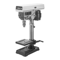
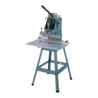
Fig. 11
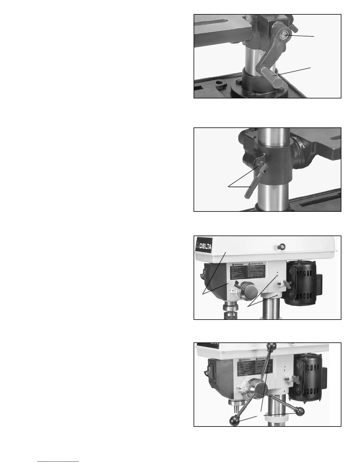
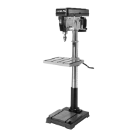
Fig. 12
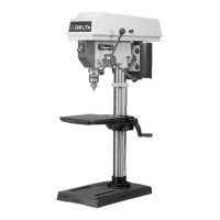
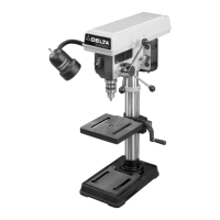
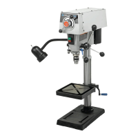
Fig. 13
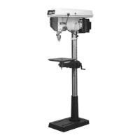
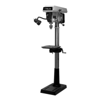
Fig. 14
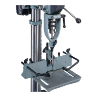
7. Figure 11, illustrates the table raising and lowering
handle (K) assembled to worm gear shaft (G).
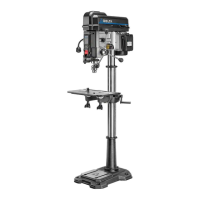
8. Thread table clamp (M) Fig. 12, into hole in rear of
table bracket, as shown.
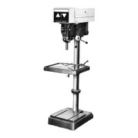
9. Place the drill press head (N) Fig. 13, onto the
column as far as it will go. Line up drill press head with
base and tighten two screws (0) with wrench provided.
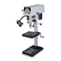
10. Thread the three pinion shaft handles (P) Fig. 14, into
the three tapped holes located in the pinion shaft, as
shown.
G
K
M
N
O
P