EasyManua.ls Logo

Delta 36-T30 - User Manual

Delta 36-T30
14 pages
Print Icon
To Next Page IconTo Next Page
Loading...
Fence System
www.DeltaMachinery
.com
Instruction Manual
To reduce risk of serious injury, thoroughly read and comply with all warnings and instructions in this manual and on product.
KEEP THIS MANUAL NEAR YOUR SAW FOR EASY REFERENCE AND TO INSTRUCT OTHERS.
36-T30
T3
/36-T50
T3
36-T31
1
Question and Answer IconNeed help?

Do you have a question about the Delta 36-T30 and is the answer not in the manual?

Summary

Important Safety Instructions

Safety Logos

Explains safety symbols used in the manual and on the product.

General Safety Warnings

Electrical Safety

Precautions for safe electrical connections and usage.

Personal Safety

Recommendations for user protection and safe operation.

Assembly

Install Front Guide Rail

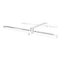
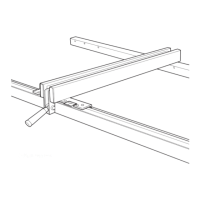
Step-by-step guide to installing the front guide rail.

Attach Rear Guide Rail

Instructions for attaching the rear guide rail to the table.

Attach Guide Tube

Instructions for attaching the fence guide tube to the front guide rail.

Install the Fence

Steps for placing and locking the fence onto the guide tube.

Operation and Adjustments

Aligning the Fence to the Miter Gauge Slots

How to align the fence parallel to the miter gauge slots.

Squaring the Fence to the Table

Procedure to ensure the fence is perpendicular to the table.

Troubleshooting

Parts, Service or Warranty Assistance

Overview

This document is an instruction manual for the DELTA® Fence System, specifically models 36-T30, 36-T50, and 36-T31. It provides detailed information on the functional description, assembly, operation, adjustment, maintenance, and warranty of the fence system.

Function Description:

The DELTA® 36-T30 and 36-T50 Fence Systems are designed to enhance the functionality of table saws by providing a precise and secure fence for guiding workpieces during cutting operations. The system includes a Fence Assembly, Front Rail, Rear Rail, and Front Guide Tube, along with necessary mounting hardware. These components allow for assembly on most DELTA® Table Saws and some non-DELTA® Table Saws. The 36-T50 system additionally includes an Accessory Leg Kit for use with a Wooden Extension Table, which can be purchased separately or constructed following the manual's instructions. The illustrations in the manual primarily depict the 36-T30 fence system installed on a DELTA® 36-729 table saw, serving as a guide for technique, as specific configurations and hardware may vary depending on the saw model.

Important Technical Specifications:

While the manual does not list specific technical specifications like dimensions or weight for the fence system itself, it details the hardware components included for assembly. These include various screws, nuts, washers, and a rail alignment gauge. For instance, the 36-T30 hardware package includes 5/16" External Tooth Lockwashers (14), 5/16" Hex Flange Nuts (17), 5/16" Countersunk Screws (8), 1/4" Pan Head Screws with Washer (4), 5/16" Hex Socket Screws (17), 1/4-20 x 1/2" Hex Cap Screws (2), and a Rail Alignment Gauge (1). The 36-T50 hardware package is more extensive, including additional items like 7/32 x 1/2" Flat Washers (4), 1/4-20" Hex Nuts (12), 3/8-16" Hex Nuts (2), #10-32" Hex Nuts (4), 5/16" x 5/8" Flat Washers (12), 10-32 x 1 3/4" Pan Head Bolts (4), #8 x 3/4" Wood Screws (8), 1/4-20 x 1-1/2" Hex Head Screws (6), 1/4-20 x 1 1/2" Countersunk Screws (6), and Leveling Feet (2). The manual emphasizes that not all hardware types and sizes may be necessary for every saw, and users should select the best fit for secure attachment.

Usage Features:

The DELTA® Fence System offers several usage features designed for precision and ease of operation.

  • Assembly: The assembly process involves attaching the Front Guide Rail, Rear Guide Rail, and Guide Tube to the table saw. For the 36-T50 model, an Extension Table and Support Legs can also be constructed and attached. The manual provides step-by-step instructions for aligning and securing these components, including using a rail alignment gauge to ensure parallelism with the table top.
  • Fence Installation: The fence itself is placed on the Guide Tube and guided over the Rear Guide Rail. A clamping lever is used to lock the fence in place, ensuring the clip on the back of the fence engages the Rear Guide Rail.
  • Alignment to Miter Gauge Slots: The fence can be aligned parallel to the miter gauge slots by adjusting two set screws on the fence. This ensures accurate cuts. The process involves moving the fence, locking it, and then adjusting the set screws with a 3mm Hex Wrench until the fence edge is parallel to the miter gauge slot.
  • Squaring to the Table: The fence can be squared perpendicular to the table using two nylon set screws on top of the fence. A T-Square is used to check the perpendicularity, and a flat-head screwdriver is used to adjust the set screws until the fence edge is square to the table.
  • Adjusting Tension on the Clamping Lever: The tension of the fence clamping lever can be adjusted to ensure the fence clamps easily and holds securely without moving. This involves lifting the clamping lever, removing the fence, and adjusting two adjusting screws with a 3mm Hex Wrench. The screws should be adjusted equally, and the fence should be re-checked for secure clamping and parallelism to the miter gauge slot.
  • Adjusting the Scale Pointer: The scale pointer indicates the distance between the inside face of the fence and the blade. To adjust its position for accurate measurements, a sample cut is made, and the cut piece is measured. If the measurement does not match the pointer's indication, two screws on the pointer are loosened, and the pointer is manually moved to match the sample cut length. The screws are then tightened. This process is repeated for the second pointer if the fence is moved to the opposite side of the blade.

Maintenance Features:

Regular maintenance is crucial for the longevity and safe operation of the DELTA® Fence System.

  • Cleaning: The machine should be kept clean by periodically blowing out air passages with dry compressed air. Plastic parts should be cleaned with a soft damp cloth, avoiding volatile solvents like gasoline, naphtha, acetone, or lacquer thinner, which can damage the material.
  • Rust Prevention: Rust-preventative oil should be removed from unpainted surfaces during unpacking using a soft cloth moistened with mineral spirits, paint thinner, or denatured alcohol. After cleaning, unpainted surfaces should be covered with a good quality household paste wax. For cast iron tables, rust can be cleaned using a medium-sized scouring pad, spray lubricant, and degreaser, followed by applying a protective product.
  • Dust Management: For optimal performance, a shop vacuum or blower should be used to keep the saw blade area, dust collection system, guarding system, and rails free of sawdust and other debris.
  • Specific Area Maintenance:
    • Riving Knife Clamp Plate: This area should be kept free of dust and debris buildup and regularly blown out with compressed air. If the riving knife clamp does not move freely, professional service is recommended.
    • Worm Gears: The worm gears should be kept free of dust and debris and regularly blown out with compressed air. A lithium-based multipurpose grease should be applied to these gears as needed.
    • Sawdust Buildup in Cabinet: Sawdust buildup inside the cabinet should be periodically cleaned, accessible from below the throat plate and inside the dust port.
  • Fence Lubrication: Paste wax should be applied weekly to the fence and guide tube sliding surfaces. Grease should be occasionally applied to the cam lock and cam foot to prevent wear.

The manual also includes important safety instructions, general safety rules, and a Proposition 65 warning regarding exposure to certain chemicals. It emphasizes the importance of reading and understanding all warnings and instructions to reduce the risk of serious injury or property damage. For service and replacement parts, users are directed to the Delta Machinery website or customer care line.

Delta 36-T30 Specifications

General IconGeneral
BrandDelta
Model36-T30
CategoryFencing & Gates
LanguageEnglish

Related product manuals