8
FIG. 4
PIN
BACK OF TABLE
FIG. 5
FIG. 6
BLADE TENSION
LEVER
FIG. 7
HEX WRENCH
BOLTS
TABLE
BOTTOM
THUMBSCREW
TOP
THUMBSCREW
FIG. 3
BEVEL SCALE
TABLE
PIN
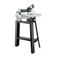
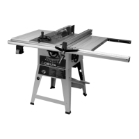
ASSEMBLING TABLE AND BLADE
ASSEMBLING TABLE
table and blade. To install the table, first insert the pin at
the back of the arm into the hole in the back of the table
against the arm and the pin is fully inserted in the table
securely attach the table to the bevel scale by tightening
the bolts shown in Figure 5.
INSTALLING THE BLADE
To reduce the risk of injury, turn unit off
and disconnect it from power source before installing
and removing accessories, before adjusting or when
making repairs.
The blade is held in place by the thumbscrew blade
clamps attached to the top and bottom arms of the scroll
Before installing a blade, make sure the blade tension
lever is moved fully to the right as shown in Figure 7.
hole in table, with the teeth facing toward the front of the
saw.
NOTE: Scroll saws cut on the downstroke, so it is
essential that teeth face forward and down.
Insert the blade into the bottom blade clamp and securely
the blade into the top blade clamp and securely tighten
Blade Tension Lever section of
this manual.)
blades.
BLADE TENSION LEVER
increase tension on the blade.
The proper degree of tension varies with different blade
tension on the blade.
As you become more accustomed to operating your
Remove the blade or release tension on the blade when