Pin Definition of Serial Communication
DOP-B07S(E)415/DOP-B07PS415 / DOP-B08S(E)515 / DOP-B10S(E)615 Series
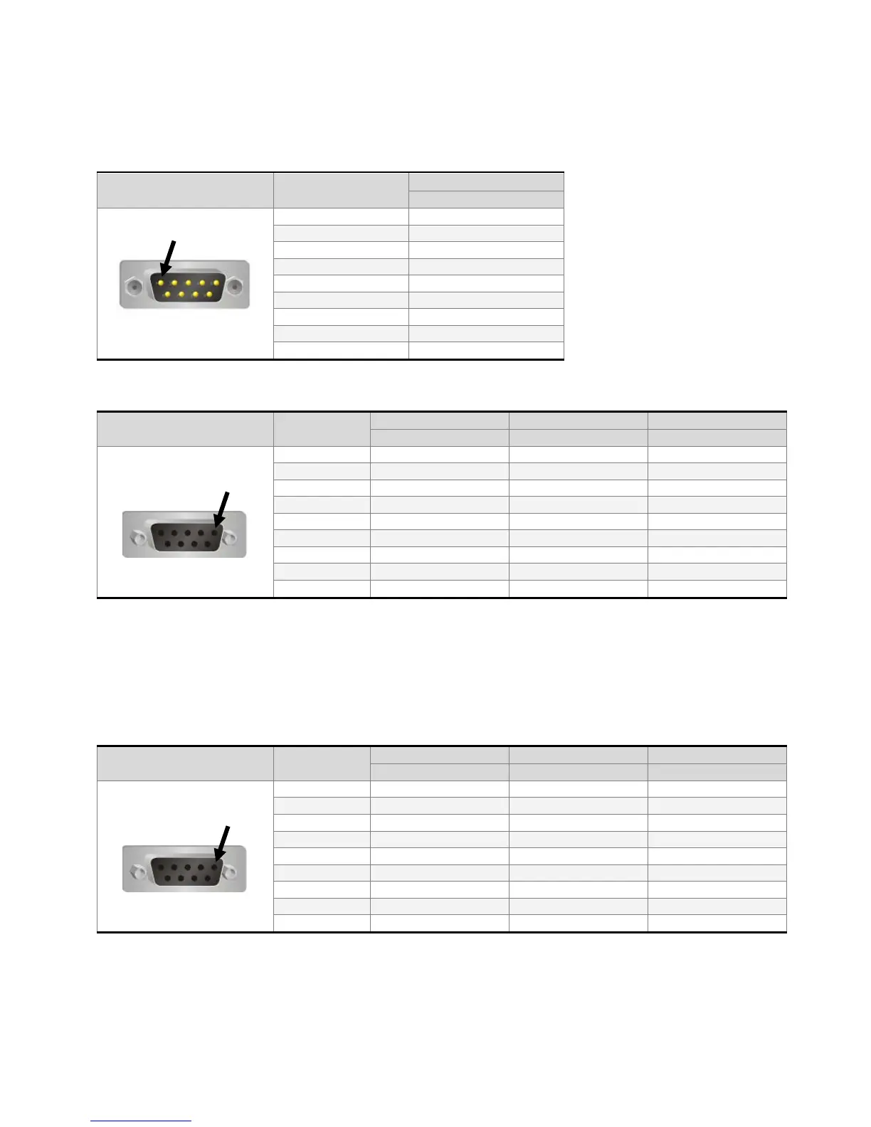
COM1 Port (Supports Flow Control)
COM Port PIN
Note: Blank = No Connection.
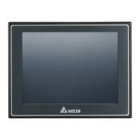
COM2 Port (Supports Flow Control)
COM Port PIN
Note1: Blank = No Connection.
Note2: When COM2 port is used for RS-232 flow control, i.e. RTS and CTS signals are used for flow control,
COM3 port will become incapable of being used.
Note3: When COM2 port is used for RS-422 flow control, please refer to the following COM3 Port signals
table for pin assignments. The signals, RTS+, CTS+, RTS- and CTS- shown in brackets are the signals
used for flow control.
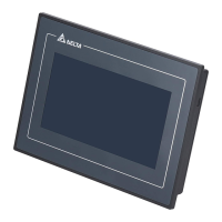
COM3 Port
COM Port PIN
Note1: Blank = No Connection.
Note2: When COM2 port is used for RS-422 flow control, please refer to the COM3 Port signals table above
for pin assignments. The signals, RTS+, CTS+, RTS- and CTS- shown in brackets are the signals used
for flow control.