Do you have a question about the Delta DOP-B and is the answer not in the manual?
General safety warnings for HMI installation, operation, and maintenance.
Key steps and precautions for installing the HMI.
Essential guidelines and precautions for HMI wiring.
Instructions for proper operation of the HMI.
Procedures for maintaining and inspecting the HMI.
Specific methods and cautions for wiring the HMI.
Guidelines for proper communication wiring.
Environmental requirements for installation and storage.
Important notes and considerations for HMI installation.
Step-by-step guide for installing the HMI.
Key notes and safety guidelines for wiring.
Essential checks before operating the HMI.
Pin assignments for the COM1 serial port.
Pin assignments for the COM2 serial port.
Pin assignments for the COM3 serial port.
Pin assignments for the Ethernet LAN port.
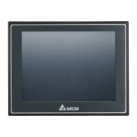
Front and rear views of DOP-B05S100/B05S101 models.
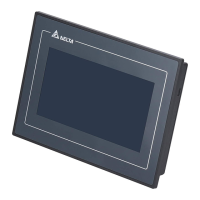
Front and rear views of DOP-B07S/PS series models.
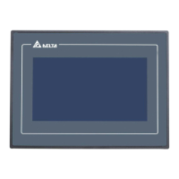
Front view of DOP-B07S(E)415/PS415 models.
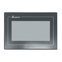
Front and rear views of DOP-B08S(E)515 models.
Front and rear views of DOP-B10S(E)615 models.
Panel cut-out dimensions for DOP-B05S100/B05S101.
Panel cut-out dimensions for DOP-B07S(E)415/PS415.
Panel cut-out dimensions for DOP-B07S(E)515/PS515.
Panel cut-out dimensions for DOP-B08S(E)515.
Panel cut-out dimensions for DOP-B10S(E)615.
| Power Supply | 24 VDC |
|---|---|
| Display | TFT LCD |
| Resolution | 800 x 480 pixels |
| Touch Panel | Yes |
| Communication Ports | USB, RS-232, Ethernet |
| Memory | 128 MB Flash |
| Operating Temperature | 0°C to 50°C |
| Size | 7-inch |