10
5.1 Wiring on the Back
This chapter illustrates how the wiring on the back is done.
Note:
■
To avoid electric shock, do not alter wiring when the power is on.
■
As there is no power switch on the power meter, be sure to install a breaker switch on the power
cord for the meter.
Recommended wiring materials are shown below:
Connecting Terminals Wire Diameters Screw Turning Torque
Functional Power AWG 10~24 7.14 kgf-cm (0.7 N*m)
Measured Voltage AWG 10~26 7.14 kgf-cm (0.7 N*m)
Measured Current AWG 14~22 8.0 kgf-cm (0.79 N*m)
RS-485 AWG 14~28 2.04 kgf-cm (0.2 N*m)
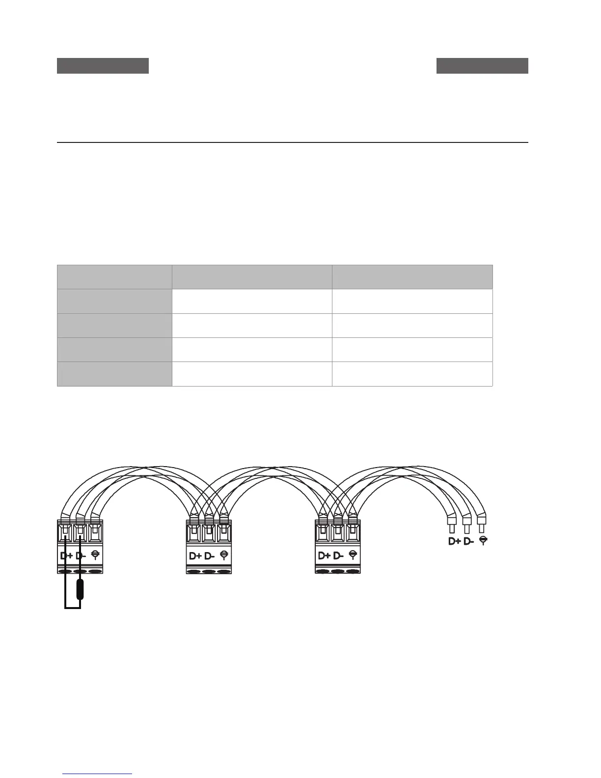
RTwisted pair cables must be used in cabling for RS485 communication. When connecting multiple
devices in series, the wiring method is displayed in the diagram below.
The D+ communication terminal for all devices should be connected on the same twisted pair cable. The
D- terminals should be connected on the other twisted pair cable. The insulation net is grounded. The
device on the end terminal needs to have terminal resistor installed on it.
Wiring Diagrams
Terminal Resistor