Do you have a question about the Delta DT3 Series and is the answer not in the manual?
| Series | DT3 Series |
|---|---|
| Type | Controller |
| Control Mode | PID Control |
| Input Type | Thermocouple, RTD |
| Output Type | Relay |
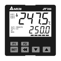
| Display | Dual 7-segment LED |
| Power Supply | 100 ~ 240VAC, 50/60Hz or 24VDC (depending on model) |
| Communication | RS-485 |
| Output Voltage | Depends on model |
| Output Current | Depends on model |
| Power | Depends on model |
| Operating Temperature | 0°C to 50°C |
| Dimensions | Depends on model |
| Weight | Depends on model |
Warning about electric shock hazards during operation and maintenance.
General warning for open-type controllers and potential dangers.
Lists supported sensor types like Thermocouple and RTD.
Details the available control algorithms such as PID, FUZZY, and MANUAL.
Specifies the types and ratings of control outputs available.
Sets the temperature set point and displays the process value.
Sets the mode for Alarm 1.
Sets the lower limit for Alarm 1.
Configures the input type for temperature sensors.
Defines the upper limit for the temperature sensor.
Defines the lower limit for the temperature sensor.
Selects the control mode (ON-OFF, PID, MANUAL, FUZZY).
Sets the communication address.
Activates Auto-Tuning to find optimal PID parameters.
Sets the Proportional band value for PID control.
Sets the Integral time value for PID control.
Sets the Derivative time value for PID control.
Sets the input filter factor for PV.
Adjusts input compensation of PV.
Sets upper limit compensation for Analog Output 1.
Configures the function for Event 1 input.
Selects the PID group for parameter setting.
Sets the target temperature for PID group 0.
Chooses the pattern number to edit.
Sets the temperature for step 0 of pattern 0.
Provides a table mapping input sensor types to register values and temperature ranges.
Sets the input filter factor for the Process Value (PV).
Adjusts the input compensation value for the PV.
Adjusts the gain for linear compensation.
Configures the controller with one output control.
Configures the controller with a second output control.
Configures the controller for ON-OFF control operation.
Configures the controller for PID control operation.
Sets a static target temperature value.
Configures a temperature profile using patterns and steps.
Sets the controller to accept target values remotely.
Configures the controller for PID control operation.
Configures the controller for PID control operation.
Adjusts PID parameters and sets the control period.
Configures the controller for manual control operation.
Adjusts the Fuzzy Gain parameter.
Sets the deadband for Fuzzy control.
Configures the system to use a single set of PID parameters.
Performs automatic tuning to determine PID parameters.
Automatic PID parameter generation via full output oscillation.
PID parameter calculation from temperature alteration slope.
Defines the function for each Event input (EV1-EV3).
Enables switching between RUN and STOP controller states.
Configures menu visibility and password protection.
Sets the delay time before an alarm activates.
Alarm triggers on PV exceeding SV limits by a set value.
Alarm triggers on PV exceeding absolute high or low limits.
Triggers if the sensor connection is incorrect or disconnected.
Selects the alarm mode from 19 different options.
Sets the upper limit for deviation alarms.
Configures the delay time for alarm activation.
Provides a map of register addresses and their content.
Sets the proportional band parameter.
Sets the integral time parameter.
Sets the derivative time parameter.
Selects the active PID parameter set.
Defines the type of Alarm 1.
Sets the upper limit for Alarm 1.
Enables or disables Auto-Tuning control.
Selects the control mode for the Process Value.
Selects the mode for setting the Set Value (SV).
Sets the gain value for Fuzzy control.
Configures the controller's RUN/STOP state.
Defines the format for communication transmission.
Specifies the panel cutout dimensions for the 4848 model.
Specifies the panel cutout dimensions for the 4896 model.