0 : No interface
1 : RS-485
Current Transformer
(CT) Function
(Optional)
None : No CT function (Current transformer is not provided)
T : Current transformer is provided (only DTA7272 series
support this function)
Current Transformer (CT) Function
The Current Transformer (CT) function is used with the alarm output. When using a
current transformer (CT) with the controller, change the corresponding alarm output
mode to mode 13 (alarm output set value is 13), then turn to operation mode and set the
current lower-limit and current upper-limit. You can set current alarm range between 0.5A
~ 30A, display resolution is 0.1A and measure accuracy is +/- 0.5A.
Communication Parameters List
Controller offers a RS-485 port for serial communication.
• Supporting transmission speed: 2400, 4800, 9600, 19200, 38400bps
• Communication protocol: Modbus (ASCII)
• Non-supported formats: 7, N, 1 or 8, O, 2 or 8, E, 2
• Available communication address: 1 to 255, 0 is broadcast address
• Function code: 03H to read the contents of register (Max. 3 words).
06H to write 1 (one) word into register.
Address Content Explanation
4700H (R) Process value (PV)
Measuring unit is 0.1, updated one
time in 0.5 second
4701H Set point (SV)
Unit is 0.1,
o
C or
o
F
4702H Upper-limit alarm 1
4703H Lower-limit alarm 1
4704H Upper-limit alarm 2
4705H Lower-limit alarm 2
4706H Upper-limit of temperature range
The data content should not be
higher than the temperature range
4707H Lower-limit of temperature range
The data content should not be
lower than the temperature range
4708H PB Proportional band 0.1 to 999.9, unit is 0.1
4709H Ti Integral time 0 to 9999
470AH Td Derivative time 0 to 9999
470BH Heating/Cooling hysteresis 0 to 9999
470CH~ 470FH Reserved
4710H Input temperature sensor type
Please refer to the contents of the
“Temperature Sensor Type and
Temperature Range” for detail
4711H Control method
0: PID (default), 1: ON/OFF,
2: manual tuning
4712H Heating/Cooling control cycle 1 to 99 second
4713H
Proportional control offset error
value
0% to 100%
4714H Temperature regulation value -999~999, unit: 0.1
4715H Alarm 1 type
Please refer to the contents of the
“Alarm Outputs” for detail
4716H Alarm 2 type
Please refer to the contents of the
“Alarm Outputs” for detail
4717H Temperature unit display selection
o
C : 1 (default),
o
F : 0
4718H Heating/Cooling control Selection Heating: 0 (default), Cooling: 1
4719H Control Run/Stop setting Run: 1 (default), Stop:0
471AH Communication write-in selection
Communication write in disabled: 0
(default), Communication write in
enabled: 1
471BH Software version V1.00 indicates 0 x 100
4729H AT Setting OFF: 0 (default), ON:1
Code 0 Normal operation (No error)
Code 1 Initial process
Code 2
Initial status (Temperature is not
stable)
Code 3
Temperature sensor is not
connected
Code 4 Temperature sensor input error
Code 5
Measured temperature value
exceeds the temperature range
Code 6 No Int. error
472BH (R)
Code 7 EEPROM Error
4733H CT monitor value Unit is 0.1A
Note: R means “read only” value
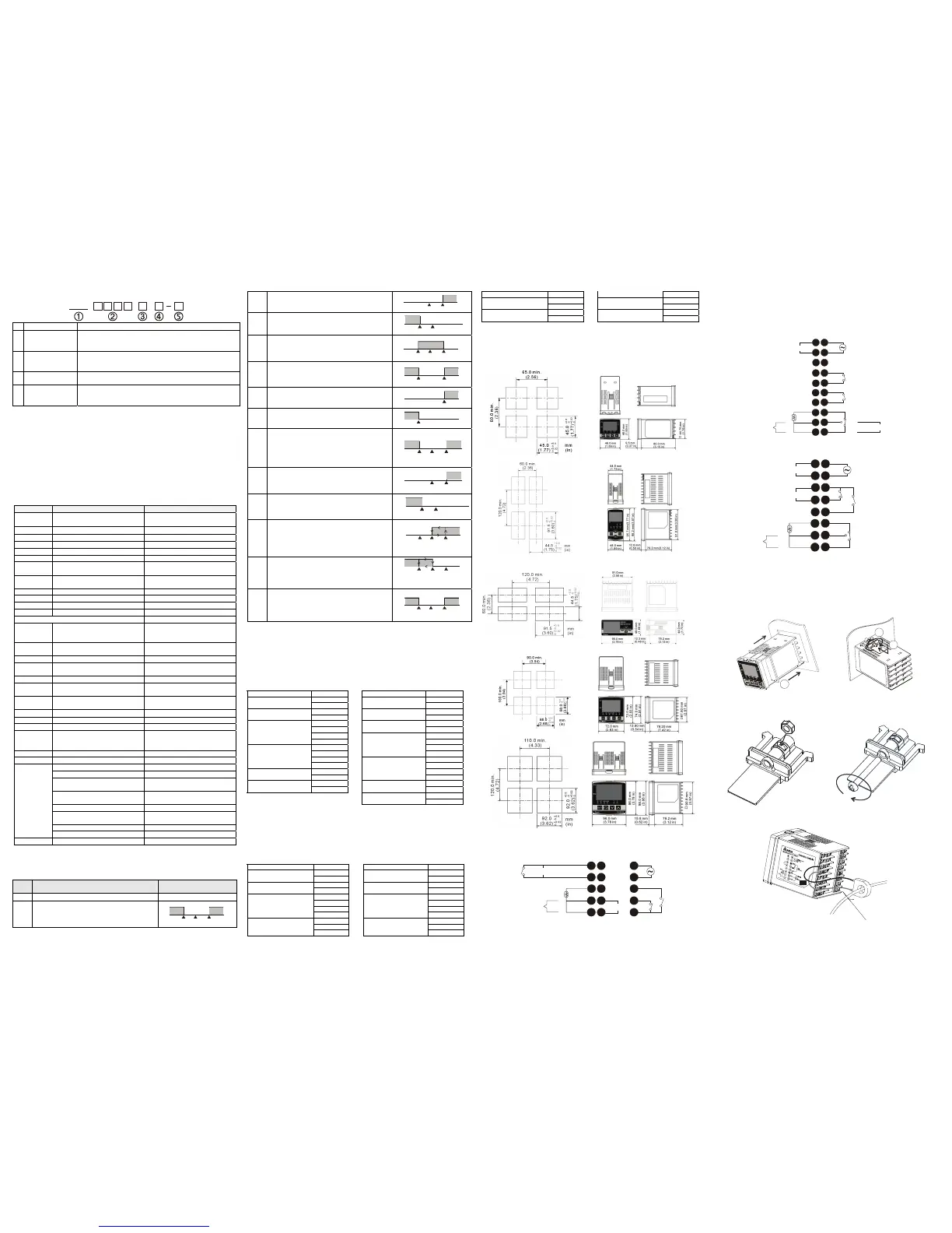
Alarm Outputs
There are up to two groups of alarm outputs and each group allows ten alarm types in
the initial setting mode. The alarm output is activated whenever the process temperature
value (PV) is getting higher or lower than the set point of alarm limit.
Set
Value
Alarm Type Alarm Output Operation
0 Alarm function disabled Output OFF
1
Deviation upper- and lower-limit:
This alarm output operates when PV value is
higher than the setting value SV+(AL-H) or lower
than the setting value SV-(AL-L).
ON
OFF
SV-(AL-L)
SV
SV+(AL-H)
2
Deviation upper-limit:
This alarm output operates when PV value is
higher than the setting value SV+(AL-H).
ON
OFF
SV
SV+(AL-H)
3
Deviation lower-limit:
This alarm output operates when PV value is
lower than the setting value SV-(AL-L).
ON
OFF
SV
SV-(AL-L)
4
Reverse deviation upper- and lower-limit:
This alarm output operates when PV value is in
the range of the setting value SV+(AL-H) and SV-
(AL-L).
ON
OFF
SV
SV-(AL-L)
SV+(AL-H)
5
Absolute value upper- and lower-limit:
This alarm output operates when PV value is
higher than the setting value AL-H or lower than
setting value AL-L.
ON
OFF
AL-L
AL-H
6
Absolute value upper-limit:
This alarm output operates when PV value is
higher than the setting value AL-H.
ON
OFF
AL-H
7
Absolute value lower-limit:
This alarm output operates when PV value is
lower than the setting value AL-L.
ON
OFF
AL-L
8
Deviation upper- and lower-limit with standby
sequence:
This alarm output operates when PV value
reaches set value (SV value) and the value is
higher than the setting value SV+(AL-H) or lower
than the setting value SV-(AL-L).
ON
OFF
SV
SV-(AL-L) SV+(AL-H)
9
Deviation upper-limit with standby sequence:
This alarm output operates when PV value
reaches set value (SV value) and the reached
value is higher than the setting value SV+(AL-H).
SV+(AL-H)
ON
OFF
SV
10
Deviation lower-limit with standby sequence:
This alarm output operates when PV value
reaches the set value (SV value) and the reached
value is lower than the setting value SV-(AL-L).
SV-(AL-L)
ON
OFF
SV
11
Hysteresis upper limit alarm output: this alarm
output operates if PV value is higher than the
setting value SV+(AL-H). This alarm output is
OFF when PV value is lower than the setting
value SV+(AL-L).
ON
OFF
AL-L
SV
AL-H
12
Hysteresis lower limit alarm output: this alarm
output operates if PV value is lower than the
setting value SV-(AL-H). This alarm output is
OFF when PV value is higher than the setting
value SV-(AL-L).
ON
OFF
AL-H AL-L
SV
13
CT alarm output:
This alarm operates when the current measured
by transformer (CT) is lower than AL-L or higher
than AL-H (This alarm output is available only for
the controller with current transformer).
ON
OFF
AL-L
SV
AL-H
Note: AL-H and AL-L include AL1H, AL2H and AL1L, AL2L.
With standby sequence: It means that the alarm output would be temporarily disabled
until the PV value reaches the set value. Then, the alarm output will operate.
Communication Protocol
Command code to read N words: 03H. The maximum value of N is 3.
For example, in order to read two words from controller 01 (address 01H) at starting data
address 4700H, the command in ASCII mode is:
ASCII mode:
Command message: Response message:
STX ‘:’ STX ‘:’
‘0’ ‘0’ ADR1
ADR0
‘1’
ADR1
ADR0
‘1’
‘0’ ‘0’ CMD1
CMD0
‘3’
CMD1
CMD0
‘3’
‘4’ ‘0’
‘7’
Number of data
(count by byte)
‘4’
‘0’ ‘0’
Starting data address
‘0’ ‘1’
‘0’ ‘9’
‘0’
Content of start address
4700H
‘0’
‘0’ ‘0’
Number of data (count
by word)
‘2’ ‘0’
‘B’ ‘0’ LRC CHK 1
LRC CHK 0
‘3’
Content of start address
4701H
‘0’
CR ‘6’ END 1
END 0
LF
LRC CHK 1
LRC CHK 0
‘7’
CR
END 1
END 0
LF
LRC check:
LRC check is the added sum from “Address” to “Data content”. For example, 01H + 03H + 47H
+ 00H + 00H + 02H = 4DH, then take the complementary of 2, B3H.
Command code to write 1 word: 06H
For example, in order to write 1000 (03E8H) in controller 01 (comm. address 01H) at the
starting data address 4701H, the command in ASCII mode is:
ASCII mode:
Command message: Response message:
STX ‘:’ STX ‘:’
‘0’ ‘0’ ADR1
ADR0
‘1’
ADR1
ADR0
‘1’
‘0’ ‘0’ CMD1
CMD0
‘6’
CMD1
CMD0
‘6’
‘4’ ‘4’
‘7’ ‘7’
‘0’ ‘0’
Starting data address
‘1’
Starting data address
‘1’
‘0’ ‘0’
‘3’ ‘3’
Data content
‘E’
Data content
‘E’
‘8’ ‘8’
‘C’ ‘C’ LRC CHK 1
LRC CHK 0
‘6’
LRC CHK 1
LRC CHK 0
‘6’
CR CR END 1
END 0
LF
END 1
END 0
LF
Panel Cutout & External Dimensions
1. Panel wall thickness should range from 1mm to 8mm
2. Provide at least 90 mm clearance around the controller for proper ventilation.
(Dimensions are in millimeter and (inch))
DTA 4848
DTA 4896
DTA9648
DTA7272
DTA9696
Terminals Identification
DTA4848
1
2
5
6
8
7
4
3
9
12
13
14
15
11
10
DC 4~20mA
5A 250Vac
RTD
Tc
14Vdc
 Loading...