Appedndix B Setting and Using an Ethernet PLC/Module
B-23
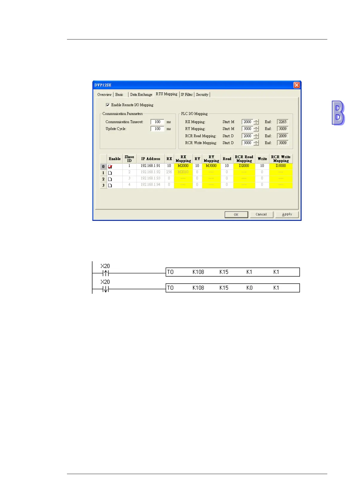
3. Use DCISoft for DVP-SE to set start addresses and numbers. (RX: M2000~M2009; RY:
M3000~M3009; RCR (Reading): D2000~D2009; RCR (Writing): D3000~D3009)
4. Edit a ladder diagram, and download it to DVP-SE. The program edited is like the one shown
below.
Description:
(1) Enabling mapping: CR15=1
(2) Disabling mapping: CR15=0
(3) After CR#15 is enabled, M2000~M2009 and D2000~D2009 will be used to read data, and
present values will be read before M3000~M3009 and D3000~D3009 are used to write
data.
※ During the execution of mapping, other devices can not be used to modify the values in
mapping registers.
※ If DVPEN01-SL is used, K108 will be changed to the number assigned to DVPEN01-SL. If
DVPEN01-SL is the first module connected to the left side of a PLC, K108 will be changed
to K100.
 Loading...


