DVP-ES2/EX2/EC5/SS2/SA2/SX2/SE&TP Operation Manual - Programming
C-14
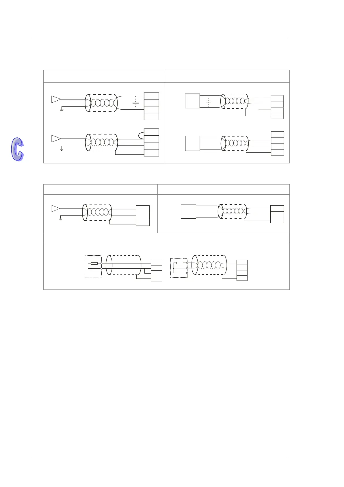
Wiring Analog / Temperature Terminals
22XA1R/T
Analog Input Analog Output
Shi elde d
cab le*1
Voltage input
Curren t i nput
Shi elde d
cab le*1
-10V~+10V
V0+
I0
V0 -
CH0
-20 mA~+2 0mA
V3+
I3
V3 -
CH3
*3
*2
FE
FE
Vol tag e outp ut
Shie lded
cabl e*1
Shiel ded
cable* 1
Current o utput
AC m otor drive, r ecorder,
proportioni ng va lve...
AC m otor drive, r ecorder,
proportioni ng valve...
V5
I5
AG
CH5
0mA~20 mA
V4
I4
AG
CH4
-10V~+ 10V
* 3
F E
FE
21EX1R/T
Analog input Analog Output
Current input
Shielded
cable*1
-20mA~+20mA
I0+
I0-
CH0
FE
Shi elded
cabl e*1
Current o utput
AC motor drive, r ecorder,
proportioni ng valve...
I2
AG
CH2
0m A~20m A
F E
Pt100
Shielded cable*4 Shielded cable*4
L3+
L3-
I3-
FE
2-wi re
L4+
L4-
I4-
FE
3 -wire
Pt100
Pt100
*1. Use shielded cables to isolate the analog input signal cable from other power cables.
*2. If the module is connected to a current signal, the terminals V3+ and I3 must be short-circuited.
*3. If variability in the input voltage results in interference within the wiring, connect the module to a
capacitor with a capacitance between 0.1–0.47 μF and a working voltage of 25 V.
*4. To prevent too much noise and interference, connect the FE of the shielded cable to ground.
*5. Connect the ground terminal of a power supply module and the analog input terminal FE to the
system ground and then ground the system ground or connect the system ground to a
distribution box.