- 4 -
Installation & Wiring
Installation
Install DVP10MC11T in an enclosure with sufficient
space around it to allow heat dissipation. D >
50mm (See the figure).
D
D
D
D
DVP10MC11T
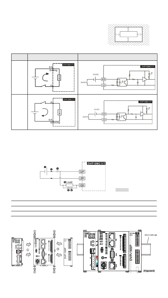
Input Point Wiring
Mode Simplified model Wiring loop
Sink
Source
Output Point Wiring
All transistor outputs in DVP10MC11T include zener diode, which is sufficient enough for
small-power conductive load and infrequent On/Off applications. However, in big-power
or frequent On/Off occasions, follow the method below to connect to suppression circuit
to reduce interferences and avoid the transistor output circuit from being damaged due
to over-voltage or overheating.
[Figure 3]
24 VDC power supply Fuse
Emergency stop button Load: Switch, conductive load
9V Zener diode, 5W (Use and when in big-power and frequent On/Off occasions)
Diode or equivalent components for suppression (Use only when in small-power loads)
Connecting to DVP-S Series Extension Modules

 Loading...


