- 3 -
A/D and D/A Specifications
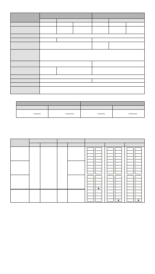
Items
Analog Input (A/D) Analog Output (D/A)
Voltage Current Voltage Current
Analog I/O range ±10V ±20mA 4 ~ 20mA
#1
±10V 0 ~ 20mA 4 ~ 20mA
#1
Digital conversion
range
±2,000 ±2,000 0 ~ +2,000 ±2,000 0 ~ +4,000 0 ~ +4,000
Resolution
#2
12-bit
Input impedance > 1MΩ 250Ω -
Tolerance carried
impedance
- ≥ 5KΩ ≤ 500Ω
Overall accuracy
Non-linear accuracy: ±1% of full scale within the range of PLC operation
temperature
Maximum deviation: 1% of full scale at 20mA and +10V
Response time 2ms (set up in D1118)
#3
2ms
#4
Absolute input
range
±15V ±32mA -
Digital data format
2’s complement of 16-bit, 12 significant bits
Average function Provided (set up in D1062)
#5
-
Isolation method No Isolation between digital circuit and analog circuit
Protection
Voltage output has short circuit protection, but a long period of short
circuit may cause internal wire damage and open circuit of current output.
#1: Please refer to the detailed explanation of D1115.
#2: Resolution formula
Analog Input (A/D) Analog Output (D/A)
Voltage Current Voltage Current
)
4000
20V
5mV(
)
4000
40mA
μΑ(10
)
4000
20V
5mV(
)
4000
20mA
μΑ(5
#3: When the scan period is longer than 2ms or the set value, the setting will follow the scan
period.
#4: When the scan period is longer than 2ms, the setting will follow the scan period.
#5: When the sampling range is “1”, the present value will be read.
I/O Configuration
Model
Input Output I/O configuration
Point Type Point Type Relay NPN PNP
20SX211R
8
DC
(Sink Or
Source)
6
Relay
V0+
I0+
VI0-
V1+
I1+
VI1-
V2+
I2+
VI2-
V3+
I3+
VI3-
FE
VO0
VO1
IO1
AG
S/S
X0
X1
X2
X5
X6
X7
Y0
Y1
Y2
Y3
Y4
Y5
X4
C0
C1IO0
X3
V0+
I0+
VI0-
V1+
I1+
VI1-
V2+
I2+
VI2-
V3+
I3+
VI3-
FE
VO0
VO1
IO1
AG
S/S
X0
X1
X2
X5
X6
X7
ZP
Y0
Y1
Y4
Y5
X4
UP
Y3IO0
X3
Y2
V0+
I0+
VI0-
V1+
I1+
VI1-
V2+
I2+
VI2-
V3+
I3+
VI3-
FE
VO0
VO1
IO1
AG
S/S
X0
X1
X2
X5
X6
X7
ZP
Y0
Y1
Y4
Y5
X4
UP
Y3IO0
X3
Y2
20SX211T
NPN
Transistor
20SX211S
PNP
Transistor
SX2-R/T/S 4
Analog
Input
2
Analog
output
Dimension & Installation
Please install the PLC in an enclosure with sufficient space around it to allow heat
dissipation, as shown in the [Figure 5].
Direct Mounting: Please use M4 screw according to the dimension of the product.
DIN Rail Mounting: When mounting the PLC to 35mm DIN rail, be sure to use the
retaining clip to stop any side-to-side movement of the PLC and reduce the chance of
wires being loose. The retaining clip is at the bottom of the PLC. To secure the PLC to
DIN rail, pull down the clip, place it onto the rail and gently push it up. To remove the
PLC, pull the retaining clip down with a flat screwdriver and gently remove the PLC from
DIN rail.
 Loading...


