- 3 -
Specifications of A/D, D/A and Temperature Sensors
Analog Input (A/D)
#1
Analog Output (D/A)
#1
Items
Voltage Current Voltage Current
Analog I/O range ±10V ±5V 1~5V ±20mA 4~20mA
±10V 0~20mA 4~20mA
Digital conversion
range
±32,000 0~32,000 ±32,000 0~32,000 ±2,000 0~4,000
Resolution #2 16-bit 12-bit
Input impedance > 1MΩ 250Ω -
Output impedance - 0.5Ω or lower
Tolerance carried
impedance
- > 5KΩ < 500Ω
Response time 25ms
#3
2ms
#4
Absolute input
range
±15V ±32mA -
Average function Provided (set up in D1062)
#5
-
Temperature Sensor PT100 / PT1000 Input
#1
NI100 / NI1000 Input
#1
Temperature Range -180ºC ~ 800ºC -80ºC ~ 170ºC
Digital conversion
range
-1800 ~ 8000 -800 ~ 1700
Resolution 20-bit
Response time 3-Wire: 210ms/2-Wire: 105ms
Average function Provided (set up in D1062)
#5
Overall accuracy
Non-linear accuracy: ±1% of full scale within the range of PLC operation
temperature
Maximum deviation: ±1% of full scale at 20mA and +10V
Digital data format
2’s complement of 16-bit, 12 significant bits
Isolation method No Isolation between digital circuit and analog circuit
Protection
Voltage output has short circuit protection, but a long period of short
circuit may cause internal wire damage and open circuit of current
output.
#1: Detailed explanation of D1115: (Default is HFFFF, disable all channels)
Bit15~12(D/A) Bit11~8(A/D-Ch2) Bit7~4(A/D-Ch1) Bit3~0(A/D-Ch0)
D/A output mode A/D input mode A/D input mode A/D input mode
A/D input mode:
Value 0 1 2 3 4 5
Mode PT100(2wire) NI100(2wire) PT1000(2wire) NI1000(2wire) PT100(3wire) NI100(3wire)
Value 6 7 8 9 A B
Mode PT1000(3wire) NI1000(3wire) -10V ~ +10V -5V ~ +5V +1V ~ +5V -20mA~+20mA
Value C D E F
Mode 4mA ~ 20mA Reserved Disabled
D/A output mode:
Value 0 1 2 3~E F
Mode -10V ~ +10V 0mA ~ 20mA 4mA ~ 20mA Reserved Disabled
For example: Assume A/D-Ch0 is PT100(3wire), A/D-Ch1 is PT100(2wire), A/D-Ch2 is 4mA~20mA
and D/A is 4~20mA, then the D1115 will be set to H2C04.
#2: Resolution formula
Analog Input (A/D) Analog Output (D/A)
Voltage Current Voltage Current
)
64000
20V
V312.5μ( =
)
64000
40mA
μΑ(0.625 =
)
4000
20V
5mV( =
)
4000
20mA
μΑ(5 =
#3: When the scan period is longer than 25ms, the setting will follow the scan period.
#4: When the scan period is longer than 2ms, the setting will follow the scan period.
#5: When the sampling range is “1”, the present value will be read. The setting range is 1~15.
#6: PT sensors support PT100 and PT1000. The unit of the value is 0.1
o
C. That is, 1 indicates 0.1
o
C, 2
indicates 0.2
o
C, and etc.
#7: NI sensors support NI100 and NI1000. The unit of the value is 0.1
o
C. That is, 1 indicates 0.1
o
C, 2
indicates 0.2
o
C, and etc.
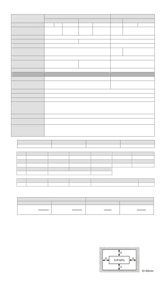
Installation
Please install the PLC in an enclosure with
sufficient space around it to allow heat dissipation,
as shown in the figure.
y Direct Mounting: Please use M4 screw
according to the dimension of the product.
y DIN Rail Mounting: When mounting the PLC to
35mm DIN rail, be sure to use the retaining clip to stop any side-to-side movement o
the PLC and reduce the chance of wires being loose. The retaining clip is at the
 Loading...


