- 6 -
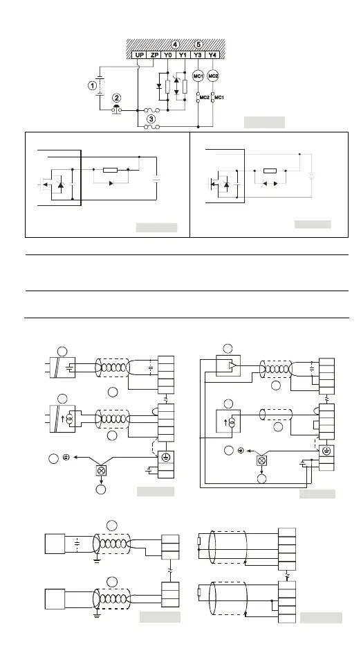
y Transistor (T) output circuit wiring
[ Figure 11 ]
VDC
+
PLC Tr an sisto r
ou tpu t
Smaller power
D
[ F ig ur e 1 2 ]
D: 1N4 001 diod e or equ ivale nt co mpo nen t
ZP
Y
UP
ZD D
VDC
+
Lar ge r po wer a nd
f req ue nt on /of f
Z D: 9V Ze ner , 5W
[ Figure 13 ]
D: 1N4 00 1 diod e or equ ivale nt co mpo ne nt
PLC Tr an sisto r
ou tpu t
ZP
Y
UP
○
1
DC power supply
○
2
Emergency stop
○
3
Circuit protection fuse
○
4
The output of the transistor model is “open collector”. If Y0/Y1 is set to pulse output, the
output current has to be bigger than 0.1A to ensure normal operation of the model.
1. Diode suppression: Used when in smaller power (Figure 12)
2. Diode + Zener suppression: Used when in larger power and frequent On/Off (Figure 13)
○
5
Manually exclusive output: For example, Y3 and Y4 control the forward running and reverse
running of the motor, forming an interlock for the external circuit, together with the PLC
internal program, to ensure safe protection in case of any unexpected errors.
Wiring of A/D, D/A, and Temperature Sensors
y A/D: Active y A/D: Passive
[ Figure 14 ]
L0+
I0+
L0-
CH0
L2+
I2+
L2-
CH2
24G
+24V
AG
FE
+
-
U
IN
+
-
U
IN
1
2
3
4
5
2
FE
AG
AGAG
1
3
4
5
[ Figure 15 ]
L0+
I0+
L0-
CH0
L2+
I2+
L2-
CH2
24G
+24V
AG
AG
-
+
U
IN
-
+
2
2
FE
FE
y D/A y PT/NI
VO+
IO+
AG
VO+
IO+
AG
CH0
CH0
[ Figure 16 ]
AC drive, recorder,
scale valu e...
AC drive, recorder,
scale valu e...
7
6
L0+
I0+
L0-
CH0
L2+
I2+
L2-
CH2
AG
AG
FE
FE
PT/NI 3-wire Sensor
PT/NI 2-wire Sensor
[ Figure 17 ]