- 7 -
○
1
Voltage input
○
2
Shielded cable
○
3
Current input
○
4
Terminal of power module
○
5
Grounding(100Ω or less)
○
6
Voltage output
○
7
Current output
Note: When the A/D module is connected to current signals, make sure to short-circuit “V+”
and “I+” terminals.
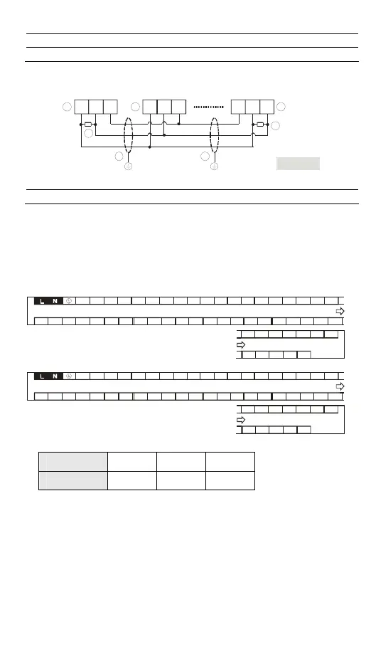
RS-485 Wiring
Figure 18
D+ D- SG D+ D- SG SG D+ D-
3
4
1 2
2
3
4
○
1
Master node
○
2
Slave node
○
3
Terminal resistor
○
4
Shielded cable
Note: 1. Terminal resistors are suggested to be connected to master and the last slave with
resistor value of 120Ω.
2. To ensure communication quality, please apply double shielded twisted pair cable
(20AWG) for wiring.
3. When voltage drop occurs between the internal ground references of two
systems,
connect the systems with Signal Ground point (SG) for achieving equal potential
between systems so that a stable communication can be obtained.
I/O Terminal Layouts
y DVP30EX200R
X4
X2X1
X0S/S X7X6X5
Y3
Y2Y1
Y0
C0
24G+24V
D-
Y5
Y4C1
NC
D+D-D+
X17
X16
X14
X13
X12X11
X10
Y7
Y6
Y10 VO+FE
Y11
AG
AG
L1-
L1+
AG
L0-I0+
I2+
L2+
L2-
AG
I1+
X3
X15
SG
IO+
L0+
y DVP30EX200T
X4X2X1X0S/S X7X6X5
Y3Y2Y1ZPUP
24G+24V
D- Y5Y4C1
NC
D+D-D+
X17X16X14X13X12X11X10
Y7Y6 Y10 VO+FEY11
AG
AGL1-L1+AGL0-I0+
I2+
L2+
L2-
AG
I1+
X3 X15
SG
IO+
L0+
Precision of the RTC (Second/Month)
Temperature
(°C/°F)
0/32 25/77 55/131
Maximum error
(Second)
-117 52 -132
Duration in which the RTC is latched: One week (Only version 2.00 and above are
supported.)