37
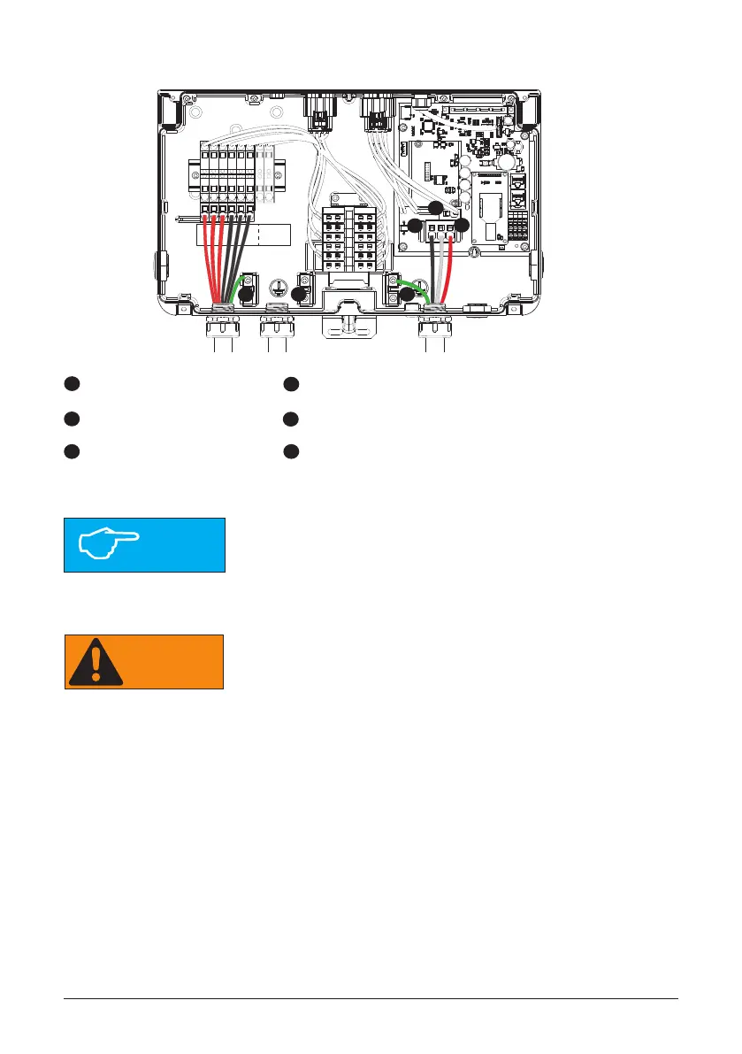
Figure 31: Wiring box AC assembly – terminal labeling
PV PV PV PV PV PV BAT BAT
1+ 2+ 3+ 1- 2- 3- + -
L1 N L2
A
B
D
L1 Terminal
N Terminal
L2 Terminal
Ground
Ground
Ground
E
B
F
C
D
E
C
Stranded copper wire should be checked so that all strands go into
the terminal opening.
Il conviendra d‘inspecter le l de cuivre multi-laire an de
s‘assurer que tous ses brins sont insérés dans l‘alésage de la
borne.
NOTICE!
AVIS!
WARNING!
AVERTISSEMENT!
AC disconnect may be required by your local AHJ. Please check
local regulations to determine if the AC disconnect is required for
your installation.
Une déconnexion du CA peut être requise par votre AHJ local.
Veuillez consulter les règlements locaux an de déterminer si la
déconnexion du CA est requise pour votre installation.
1. Mount the AC disconnect (if required by local AHJ) close enough to the inverter.
2. Install conduit tting and conduit into the wiring box compartment from AC disconnect or
utility service panel.
3. Thread the inverter’s AC output wires through cup piece of conduit and loosely t the
conduit into the inverter’s open conduit tting and the DC disconnect or junction box conduit
tting.
4. Route AC wiring through conduit and verify that the exposed wires are at least 6 inches
in length to provide adequate strain relief and wire end strip length required. Secure the
conduit into both ttings then tighten conduit ttings to manufacturer’s recommended
torque.
A
F

 Loading...


