42
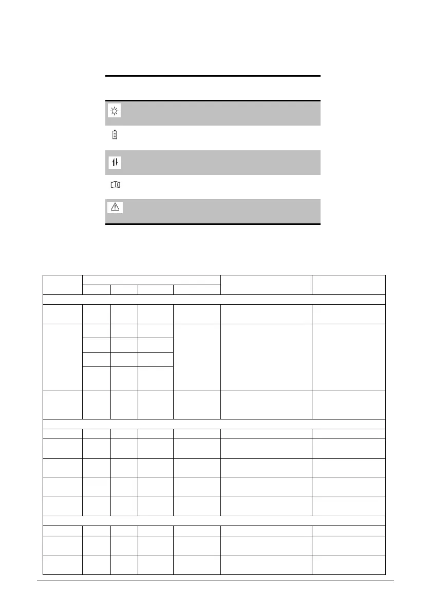
5.1.2 LED Status
Label Designation Color
Operation(OPER)
Red / Green
Battery(BAT)
Red / Green
Wireless
Communication(COMM)
Red / Green
Information(INFO)
Red / Green
Fault(FAULT)
Red / Green
5.1.3 LED Message
The LEDs indicate the operational status of the inverter
Message
Category
LED Signals Message Explanation Example
LED Color Status Behavior
OPER Led
Normal
operation
OPER Green <ON> Constant on The inverter feeds in grid.
Sync. OPER Green <BAR> Four LEDs form
a progress bar.
The inverter is synchronizing with
grid.
LED signals:
OPER LED is ON,
BAT LED is ON.
COMM LED Blinks
Message:
is 50%-75%.
BAT Green <BAR>
COMM Green <BAR>
INFO Green <BAR>
Night mode OPER Green <BLINK> 1s on, 4s off Grid is connected, but the inverter
is unable to feed in grid because
PV voltage is too low.
BAT Led
Battery fault BAT Red <ON> Constant on Battery is in fault mode.
Battery
comm. fail
BAT Yellow <ON> Constant on Battery communication timeout
Battery
standby
BAT Yellow <BLINK> 1s on, 1s off Battery is in standby mode
power
BAT Green <BLINK> 1s on, 4s off
Absolute battery power is lower
than 50W
Battery
normal
BAT Green <ON> Constant on Battery is in normal operation.
COMM Led
BLE fail COMM Red <ON> Constant on BLE is in fault mode
APP
Connected
COMM Green <ON> Constant on APP is connected
running
COMM Green <BLINK> 1s on, 1s off BLE is running Only BLINK for 2 cycles in
one minute
Firmware upgrading is ongoing
Inverter is receiving image file
External event occurs and inverter
is unable to run
Inverter initialization when grid is
changing from disconnected into
connected.

 Loading...


