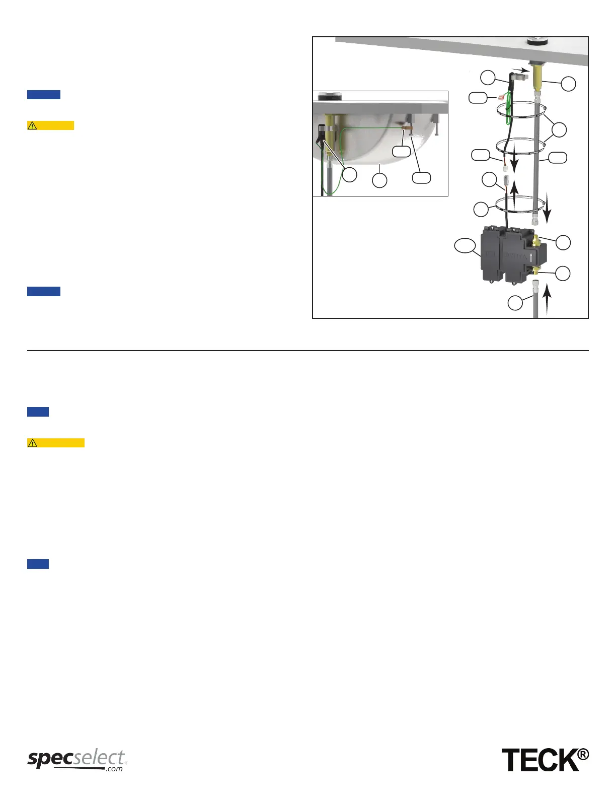
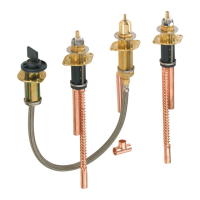
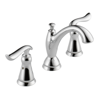
STEP 3 - FAUCET ASSEMBLY CONNECTION TO
SURFACE MOUNT BOX (see Figure 3)
1. Connect the polymer braided hose (ZB*) from the faucet (ZA*) to the
solenoid outlet adapter (I-1).
2. Connect the polymer braided hose (L) from the water supply to the
solenoid inlet adapter (I-2).
Non-conductive polymer braided hose must be used as supply lines
going to and from the solenoid for the sensor to function properly.
3. Connect the sensor module (K) onto the faucet shank (ZA*).
• Sensor module (K) should be oriented with the plastic head away
from conductive surfaces (especially stainless steel sinks) for proper
faucet function.
• Confirm the spout shank (ZA*) and sensor clip (K) do not touch any
conductive material, including conductive water lines, metallic sinks,
metal overflow, structural supports or other mounting hardware.
Contact may prevent sensor calibration and function.
4. Connect the sensor plug (K-1) to the the driver board plug (F), coming
from the surface mount box (A).
5. Use the cable ties (P) to secure the sensor cables to the polymer braided
hose (ZB*).
6. If the faucet is being installed on a stainless steel sink (U**), connect the
basin clip (K-2) to the sinks body/hold down hardware (U-1**), as shown
in figure 3A.
7. Turn “ON” water supply and check for leaks at all polymer braided hose
connections and solenoid a” adapters (I-1 & I-2).
• A 36” (91cm) sensor extension cable (061256A) (sold separately), can
be used to extend the sensor cable (K-1).
• A polymer braided hose (062032A) (sold separately) can be used to
extend the hoses, along with part (O) a” union.
ÉTAPE 3 - CONNEXION DE L’ENSEMBLE DE ROBINETAU BOÎTIER DE MONTAGE EN SURFACE
(voir la Figure 3)
1. Connecter l’autre extrémité du tuyau en polymère tressé (ZB*) du robinet (ZA*) à l’adaptateur de prise de solénoïde (I-1).
2. Connecter l’autre extrémité du tuyau en polymère tressé (L) de l’alimentation en eau à l’adaptateur de prise de solénoïde (I-2).
Les lignes d’alimentation vers et provenant du solénoïde doivent être des tuyaux en polymère tressé non-conducteurs pour que le capteur fonctionne
correctement.
3. Connecter le module de capteur (K) sur la tige de robinet (ZA *).
• Le module du capteur doit être orienté avec la tête en plastique dans la direction opposée des surfaces conductrices (surtout pour les éviers en acier
inoxydable)
• Confirmer que le bec (ZA*) et la pince de la sonde (K) ne touchent pas tout matériel conducteur, y compris les lignes d’eau conductrices, les
éviers métalliques, les trop-pleins en métal, des supports structurels ou d’autres pièces de fixation. Le contact peut empêcher le calibrage et le
fonctionnement du capteur.
4. Raccorder la fiche du capteur (K-1) à la prise de la carte de commande (F), en provenance de la zone de montage en surface (A).
5. Utiliser les colliers de serrage (P) pour fixer les câbles de capteur au tuyau en polymère tressé (ZB*).
6. Si le robinet est installé sur un évier en acier inoxydable (U**), connecter la pince de bassin (K-2) au corps de l’évier / maintenir enfoncé le matériel (U-1**),
comme représenté sur la figure 3A.
7. Ouvrir l’alimentation en eau « ON » et vérifier pour des fuites à tous les raccords de tuyau en polymère tressés et aux adaptateurs de solénoïde de 3/8 po
(I-1 et I-2).
• Une rallonge de capteur de 36 po (91 cm) (061256A) (vendu séparément), Peut être utilisé pour étendre le câble du capteur (K-1).
• Un tuyau de polymère tressé (062032A) (vendu séparément) peut être utilisé pour étendre les tuyaux, avec une union de 3/8 po (O).
A & C
K
I-1
ZA*
F
K-1
ZB*
L
I-2
P
P
K-2
K
U-1**
U**
A
K-2
Figure 3
* Previously installed / Installé auparavant
** Supplied by others / Fourni par d’autres.
Page - 5 of 19
214188 Rev. A