40
0V
10V
Pr.49 Pr.48
Pr.03
Pr.08
0V
10V
Pr.49Pr.48
Pr.03
Pr.08
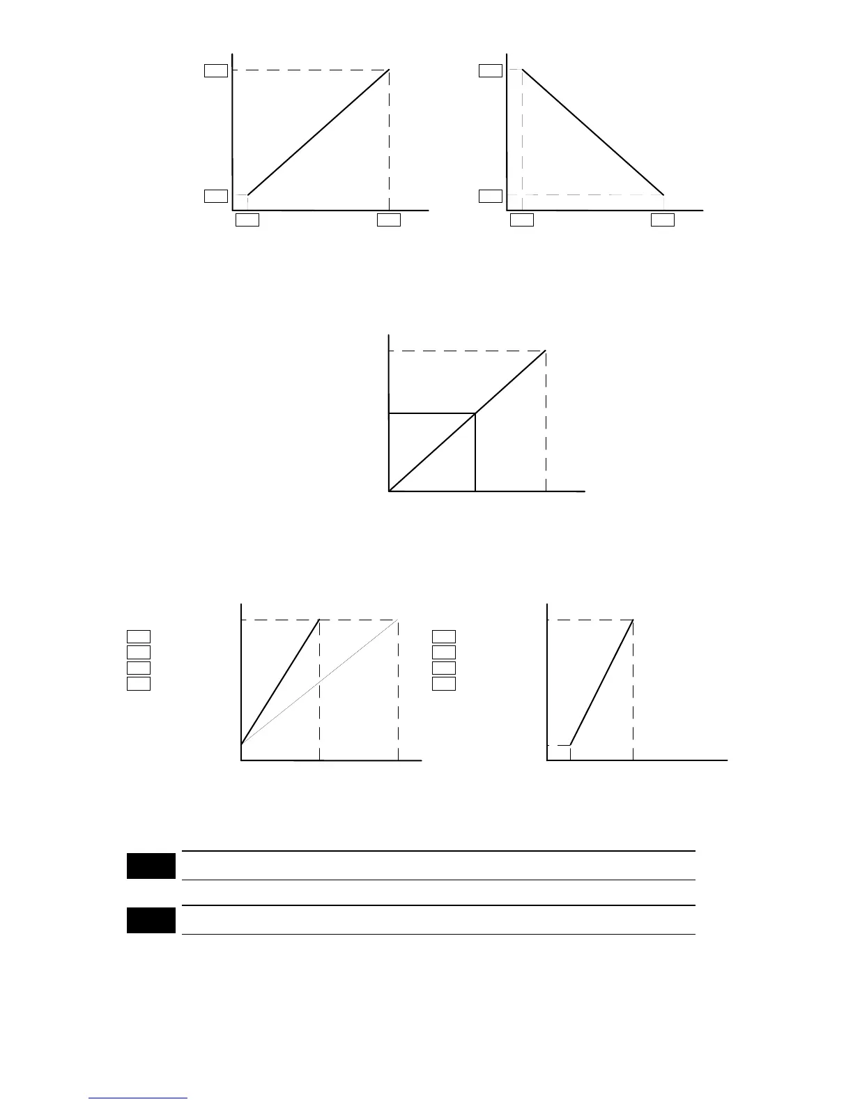
Analog input signal levelAnalog input signal level
Output frequency Output frequency
The analog input signal level is the combined input signals from the analog voltage input
(AVI) (0 - 10 V) and analog current input (ACI) (4 - 20 mA). The voltage corresponding to
the analog current input (4 - 20 mA) and analog input signal level is defined as follows:
Analog current frequency command
10 V
0 V
4 mA
20 mA
Voltage corresponding to the
analog input signal level
5 V
12 mA
An example of such application may be illustrated as follows:
Analog input signal level
0V
10V
Pr.08
Pr.03
5V
60 Hz
1.5 Hz
= 60.0 Hz
= 1.5 Hz
Pr.49
Pr.48 = 5.0 V
= 0 V
0 V
10 V
Pr.08
Pr.03
60 Hz
1.5 Hz
= 60.0 Hz
= 1.5 Hz
Pr.49
Pr.48 = 5.0 V
= 1 V
5 V1 V
Output frequency Output frequency
Analog input signal level
Pr.50
Reserved
Pr.51
Reserved