EasyManuals Logo

Delta VFD-L User Manual

Delta VFD-L
16 pages
To Next Page IconTo Next Page
To Previous Page IconTo Previous Page
Page #5 background imageLoading...
Page #5 background image
4
Main Circuit Terminals: wire gauge 22-14AWG, torque 10kgf-cm (8.7 in-lbf)
Terminal Symbols Terminal Functions
L/L1, N/L2 AC line input terminals
U/T1, V/T2, W/T3 Motor connections
Earth Ground
Control Circuit Wiring: wire gauge 22-14AWG, torque 10kgf-cm (8.7 in-lbf)
Terminal
symbols
Terminal names Remarks
M0 RUN/STOP
Normally Open contact, AC drive starts
operation when closes.
M1 FWD/REV
Normally Open contact, AC drive starts
reverse motion when closes.
MO1 Fault Indication When error is detected, MO1 will close.
RS-485
Serial Communication
Port
When DIP Switch 7 is ON, the drive is
controlled by RS-485.
DCM Digital Signal Common Ground for M0, M1 and M01
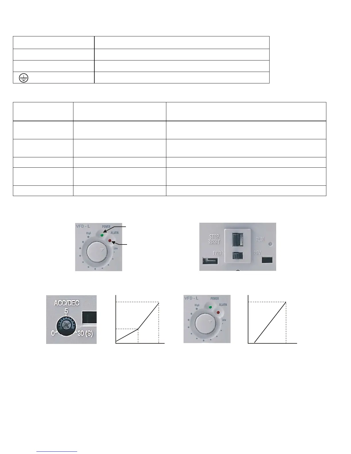
Front Panel Control Diagram
GREEN POWER LED
RED ERROR LED
(Please refer to
troubleshooting & Fault
Information)
0.05
510
30
5
Accel/Decel Time(Sec)
Unit
Accel/Decel Time Knob (sec.)
0
110
100
Output frequency (%)
9
Unit
Output Frequency Knob (Hz)

Questions and Answers:

Question and Answer IconNeed help?

Do you have a question about the Delta VFD-L and is the answer not in the manual?

Delta VFD-L Specifications

General IconGeneral
SeriesVFD-L
Control MethodV/F Control
Enclosure RatingIP20
TypeAC Motor Drive
Output Frequency1.0 ~ 400 Hz
Overload Capacity150% for 60 seconds
ProtectionOvercurrent, Overvoltage, Undervoltage, Overheating, Short Circuit
Braking UnitBuilt-in
CommunicationRS-485 (Modbus ASCII/RTU)
Operating Temperature-10°C to 50°C
Storage Temperature-20°C ~ 60°C
Humidity90% RH or less (non-condensing)
AltitudeUp to 1000m without derating
Cooling MethodFan Cooled
Input VoltageSingle-phase 200-240V

Related product manuals