Chapter 12 Descriptions of Parameter Settings | VFD-ED
Speed Unit
Control Mode
VF VFPG SVC FOCPG
FOCPM
Default: 0
Settings 0: Hz
1: m/s
2: ft/s
3: Direct docking mode only, contact Delta for more information.
Output Direction Selection
Control Mode
VF VFPG SVC FOCPG FOCPM Default: 0
Settings 0: FWD: counterclockwise, REV: clockwise
1: FWD: clockwise, REV: counterclockwise
Control Mode
VF VFPG SVC FOCPG FOCPM Default:12
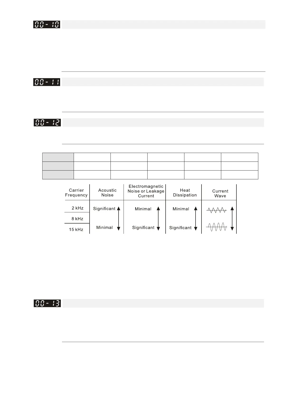
Settings 2–15 kHz
Determines the PWM carrier frequency for the AC motor drive.
Models 3–5 HP 7.5–15 HP 20–30 HP 40–60 HP 75–100 HP
Settings 2–15 kHz 2–15 kHz 2–15 kHz 2–9 kHz 2–6 kHz
Default 8 kHz 10 kHz 8 kHz 6 kHz 6 kHz
From the table, you see that the PWM carrier frequency has significant influences on the motor’s
electromagnetic noise, the AC motor drive heat dissipation, and the motor acoustic noise. Therefore, if the
surrounding noise is greater than the motor noise, lower the carrier frequency to reduce the temperature
rise. Although the motor has quiet operation in the higher carrier frequency, consider the entire wiring and
interference.
If you set the carrier frequency higher than the defaults in the table above, the motor drive derates the
capacity. See Carrier Frequency Derating Capacity (Fc) in Chapter 08.
Automatic Voltage Regulation (AVR) Function
Control Mode
VF VFPG SVC FOCPG FOCPM Default: 0
Settings 0: Enable AVR
1: Disable AVR
2: Disable AVR when decelerating to stop
The AVR function automatically regulates the AC motor drive output voltage to the motor’s rated voltage
when the input power is larger than the motor’s rated voltages. For instance, if you set V/F curve to 200
V
AC
/50 Hz and the input voltage is between 200–264 V
AC
, then the output voltage to the motor is
 Loading...