12 Descriptions of Parameter Settings | VFD-ED
You can change the terminal status between ON and OFF through communications.
For example, set MI1=1 (multi-step speed command 1) and MI2=2 (multi-step speed command 2). Then
the reverse + second step speed command = 1010 (binary) = A (hexadecimal). You only need to set
Pr.02-10=A through communications and it can move reverse at the second step speed. In this case, you
do not need to wire any multi-function terminals.
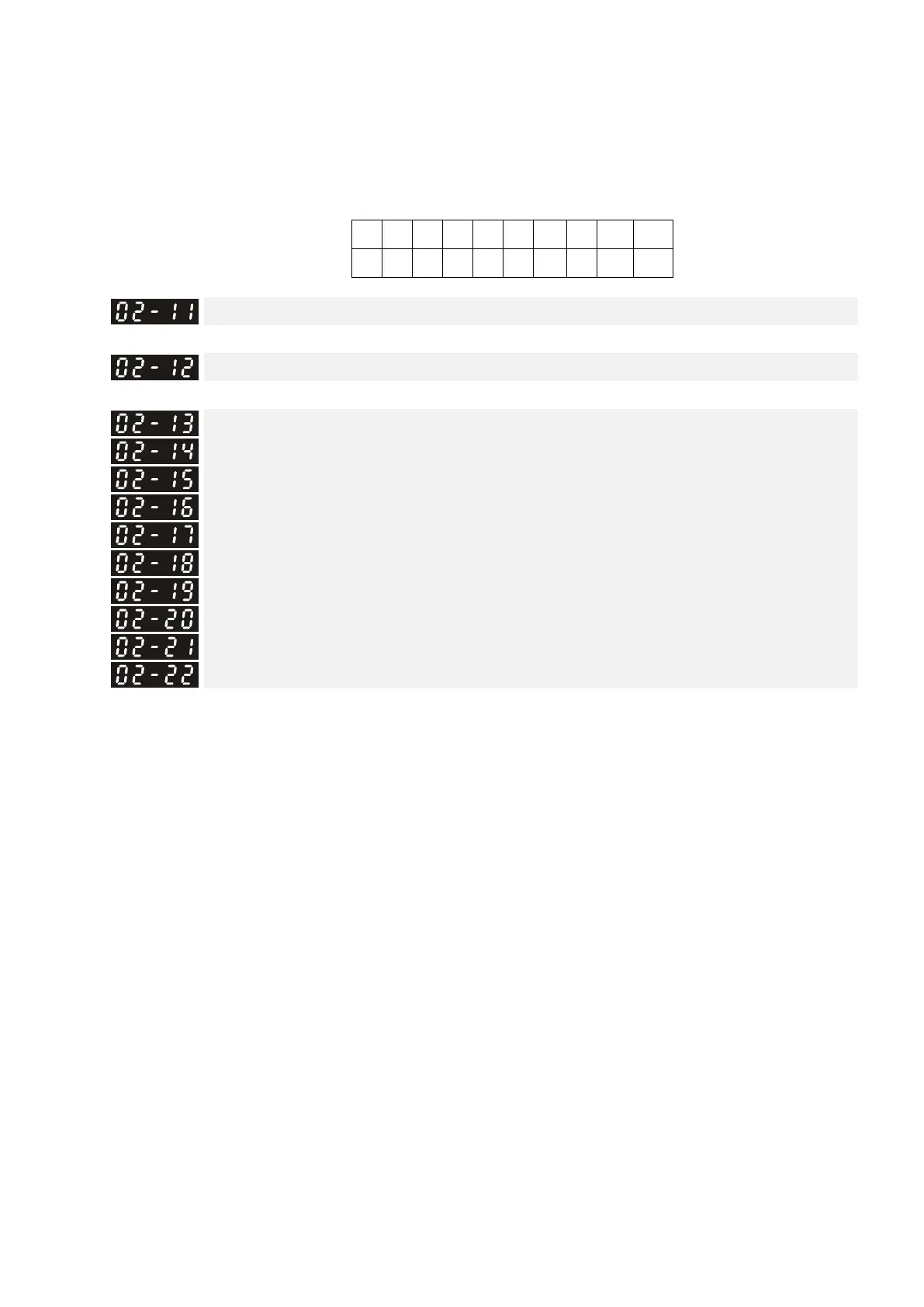
bit9
bit8
bit7
bit6
bit5
bit4
bit3
bit2
bit1 bit0
MI8
MI7
MI6
MI5
MI4
MI3
MI2
MI1
REV
FWD
Multi-function Output 1: RA, RB, RC (Relay 1)
Default: 0
Multi-function Output 2: MRA, MRB, MRC (Relay 2)
Default: 0
Multi-function Output 3: R1A, R12C (Relay 3)
Multi-function Output 4: R2A, R12C (Relay 4)
Multi-function Output 5: MO1
Multi-function Output 6: MO2
Multi-function Output 7: MO3
Multi-function Output 8: MO4
Multi-function Output 9: MO5
Multi-function Output 10: MO6
Default: 0
Settings Control Mode
VF VFPG SVC FOCPG
FOCPM
0: No function
○ ○ ○ ○ ○
1: Indication during operation
○ ○ ○ ○ ○
2: Operation speed reached
○ ○ ○ ○ ○
3: Desired frequency 1 reached (Pr.02-25, Pr.02-
26)
○ ○ ○ ○ ○
4: Desired frequency 2 reached (Pr.02-27, Pr.02-
28)
○ ○ ○ ○ ○
5: Zero Speed (Frequency command)
○ ○ ○ ○ ○
6: Zero speed with stop (Frequency command)
○ ○ ○ ○ ○
7: Over-torque (OT1) (Pr.06-05–06-07)
○ ○ ○ ○ ○
8: Over-torque (OT2) (Pr.06-08–06-10)
○ ○ ○ ○ ○
9: Drive is ready
○ ○ ○ ○ ○
10: User-defined low-voltage detection (LV)
○ ○ ○ ○ ○
11: Malfunction indication
○ ○ ○ ○ ○
12: Mechanical brake release (Pr.02-29, Pr.02-30,
Pr.02-37)
○ ○ ○ ○ ○
13: Overheat (Pr.06-14)
○ ○ ○ ○ ○
 Loading...