12 Descriptions of Parameter Settings | VFD-ED
14: d-axis current
15: d-axis feedback value
16: q-axis voltage
17: d-axis voltage
18: Torque command
19–20: Reserved
21: Power output
When setting to 0, it is output frequency, not ASR output frequency.
Analog Output Gain 1
Analog Output Gain 2
Control Mode
VF VFPG SVC FOCPG FOCPM Default: 100.0
Settings 0–200.0%
Sets the corresponding voltage for the analog output 0.
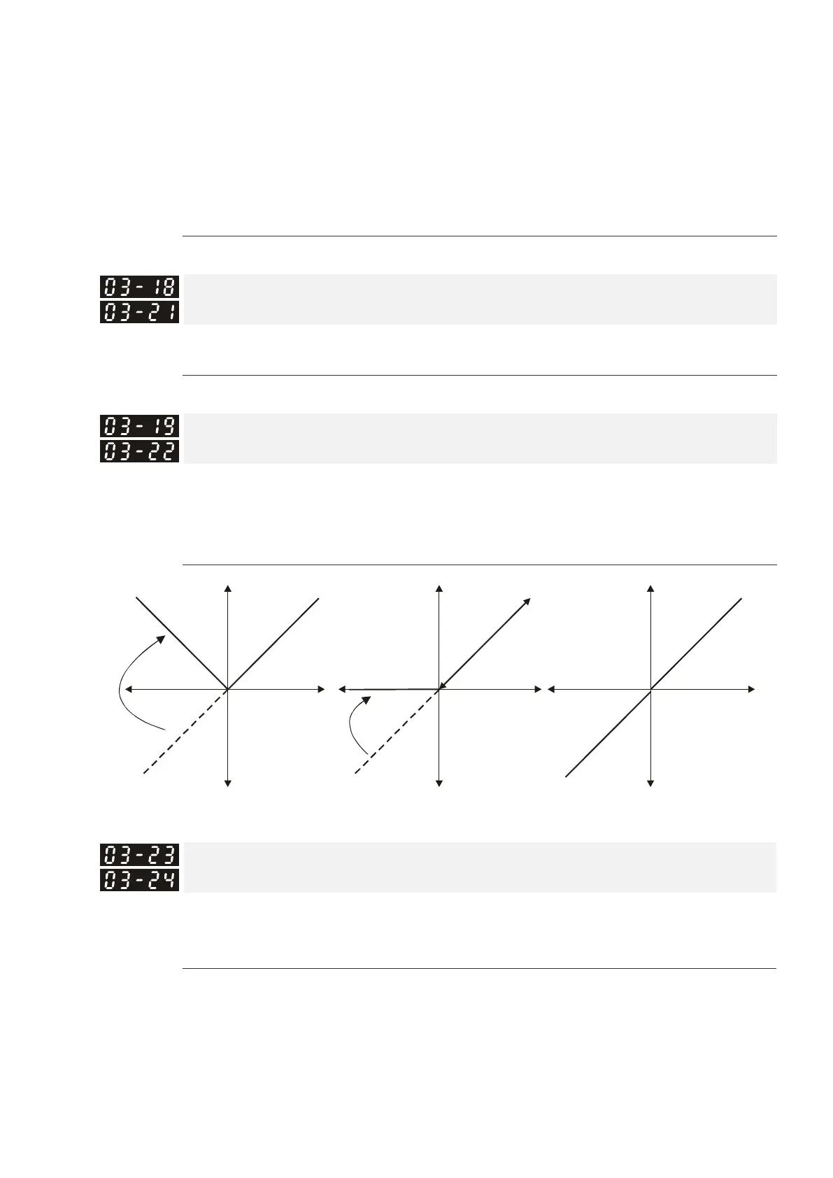
Analog Output Value in REV Direction 1
Analog Output Value in REV Direction 2
Control Mode
VF VFPG SVC FOCPG FOCPM Default: 0
Settings 0: Absolute value in output voltage
1: Output 0 V in REV direction
2: Enable output voltage in REV direction
Analog Input Type (AUI1)
Analog Input Type (AUI2)
Control Mode
VF VFPG SVC FOCPG FOCPM Default: 0
Settings 0: Bipolar (±10 V)
1: Unipolar (0–10 V)
When this parameter is set to 0 (bipolar), the input function direction is determined by the input signal.
0: And Pr.03-00=1 or 2, AUI decides the operation direction.
1: And Pr.03-00=1, the FWD/REV terminal decides the operation direction.
1: And Pr.03-00=2, setting Pr.02-01–Pr.02-08 to 39 decides the operation direction.
10V
frequency
Selection for the analog output direction
0V
03-19=0
10V
frequency
0V
03-19=1
10V
frequency
0V
03-19=2
 Loading...