Do you have a question about the DEMAG DRC-MJ D3 and is the answer not in the manual?
Provides overview of the product and its intended use for safe operation.
Explains the manual's role as an integral part and its availability.
Outlines copyright protection and intended use of the manual's content.
Overview of safety aspects necessary for user and product protection.
Explains how safety information is marked with symbols and signal words.
Details 'IMPORTANT' and 'NOTE' symbols for product use and warnings.
Describes the DRC-MJ D3 transmitter's purpose for crane control and operator positioning.
Defines responsibilities for owners and qualifications for personnel.
Outlines owner's legal product responsibility and safety obligations.
Lists required qualifications for specialist personnel.
Details activities and qualifications for operators, repair, service, and technicians.
Lists required PPE like helmets, shoes, gloves, and glasses.
Emphasizes using only genuine Demag spare parts to avoid damage.
Stresses the obligation for regular inspections of the transmitter.
Lists the items included in the complete delivery of the DRC-MJ D3 transmitter.
Details available DRC-DR and DRC-MP radio receiver models.
Lists accessories like carrying straps, chargers, and spare parts.
Describes coding labels and direction foils for crane identification.
Warns that breaking casing seals voids warranty rights.
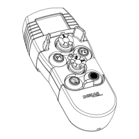
Describes mini joysticks, STOP, signal, and special function buttons.
Details screen specifications like size, color, and operating temperature.
Provides data on transmitter output, range, and frequency.
Specifies the enclosure type (IP 55).
Lists specifications for the battery charger and rechargeable battery.
Shows physical dimensions of the DRC-MJ D3 hand-held transmitter.
Instructs to check for transport damage and lodge claims if found.
Advises on proper disposal and recycling of packing materials.
Details conditions for storing the DRC radio controls and accessories.
Explains the system's design for wireless control of hoists and cranes.
Describes the 2.4 GHz ISM band transmission and frequency-hopping system.
Details power sources, battery capacity display, and charging.
Explains how battery status is shown on the transmitter screen.
Provides instructions for charging the transmitter batteries using the plug-in charger.
Guides on replacing rechargeable batteries and using primary cells.
Explains LED indicators and button symbols on the transmitter.
Details the LED indicators for operating status.
Describes the transmitter's screen and its displayed information.
Explains the Crane ID, selected crab display, and radio signal strength icon.
Details icons like battery, lock, STOP, 'no radio signal', and warning.
Explains various status icons including fault, overload, brake, and universal outputs.
States that D3 generation units are not compatible with D2 or D1 units.
Covers coding labels and direction symbols for crane identification.
Details how to use coding labels for crane ID display.
Explains the attachment and use of travel direction foils.
Warns about electric current hazards and the need for trained personnel.
Outlines crucial safety steps and the STOP button function.
Specifies target groups and their qualifications for handling the system.
Details steps for initial setup, including battery charging and crane ID.
Describes logging the transmitter onto the receiver and initial switching.
Explains the safety-relevant process of logging on a transmitter and assigning crane ID.
Details extended functions for DRC-DR systems and links to its manual.
Explains how to release a DRC radio receiver from a transmitter.
Covers logging, transferring, and logging off multiple transmitters onto one receiver.
Warns against incorrect operation leading to severe injuries or damage.
Lists target groups for operation, repair, and service, and their qualifications.
Details activities and qualifications for operators, repair, service, and technicians.
Outlines pre-operation checks for safe crane and system status.
Details the procedure to switch on the transmitter.
Lists checks for battery, signal, crane ID, horn, and STOP button.
Explains how to start crane operation using the electronic On key.
Describes the function of the electronic On key for switching modes.
Details the use of mini-joystick control elements for motion axes.
Explains the red STOP button's function for emergency stops and safe status.
Describes the signal button for acoustic signals and limit switch tests.
Mentions these keys control various functions based on receiver/system design.
Explains how to limit motion speeds and activate the function.
Provides steps to activate the speed-limit function.
Provides steps to deactivate the speed-limit function.
Instructs on switching to Standby or off to reduce power and prevent unauthorized use.
Advises on fully charging and removing batteries for long-term storage.
Details the different operating statuses of the transmitter.
Describes the state when the transmitter is off, with very low power consumption.
Explains STOP mode, red LED, and no command transmission.
Details Run mode, green LED, and full transmitter functionality.
Describes Standby mode, lock icon, reduced power, and deactivated connection.
Explains how to reset the transmitter by removing the battery pack.
Provides steps to activate the information menu.
Guides on selecting the crane or crab control system.
Explains activating crab selection and shows the information menu start screen.
Describes how to navigate through the information list.
Lists available data codes and descriptions in the information menu.
Lists problems, screens, causes, and solutions for troubleshooting.
Continues troubleshooting common issues like battery, response, and crane ID.
Continues troubleshooting common issues like battery charging and receiver response.
Specifies personnel requirements for disposal tasks.
Details steps for recycling and disposing of components and batteries.
Explains how to contact after-sales service for technical information and spare parts.
Lists service personnel and their qualifications.
Details how to activate the parameter programming menu.
Provides detailed explanations of various programmable parameters.
Explains parameters for transmitter power, frequency, alarms, and illumination.
Allows reversing lifting/lowering direction via joystick, parameter code 507.
Explains how to navigate parameter settings.
Details how to change parameter values.
Sets whether both left joystick axes can be controlled simultaneously, code 508.
Explains navigation in entry/selection mode.
Details how to activate or deactivate the electronic gate.
Lists FCC compliance rules and conditions for device operation.
Details Industry Canada compliance rules for the device.
| Brand | DEMAG |
|---|---|
| Model | DRC-MJ D3 |
| Category | Transmitter |
| Language | English |