23
At this point you will be ready to attach
the facebow side arms. Note that they
are marked right and left and refer to the
patient’s right and left. Make sure that
the scales on the posterior reference
slides are adjusted to their zero posi-
tions.
A. Facebow Application
Remove the nylon earpieces on both
the posterior reference slides and
begin the attaching of the side arms
(fig. 43). First you will need to locate
the right side arm on the crossbar so
that the lockscrew on the crossbar
clamp faces upward and the posteri-
or reference pin at the end of the
posterior reference slide lightly
touches the posterior reference
point. Secure the side arm clamp to
the anterior crossbar. Then attach
the left side arm similarly.
B. Earbow Application
Make sure the nylon earpieces are
on both posterior reference slides.
Position the right arm on the cross-
bar so that the lockscrew on the
crossbar clamp faces upward and
the nylon earpiece fits snugly in the
external auditory meatus. Secure the
side arm clamp tightly and attach the
left side arm similarly.
At this point the facebow/earbow
records the relationship of the maxillary
dental structure to the posterior refer-
ence points. The only thing remaining to
be done is to relate the maxillary dental
structures to the anterior reference
point.
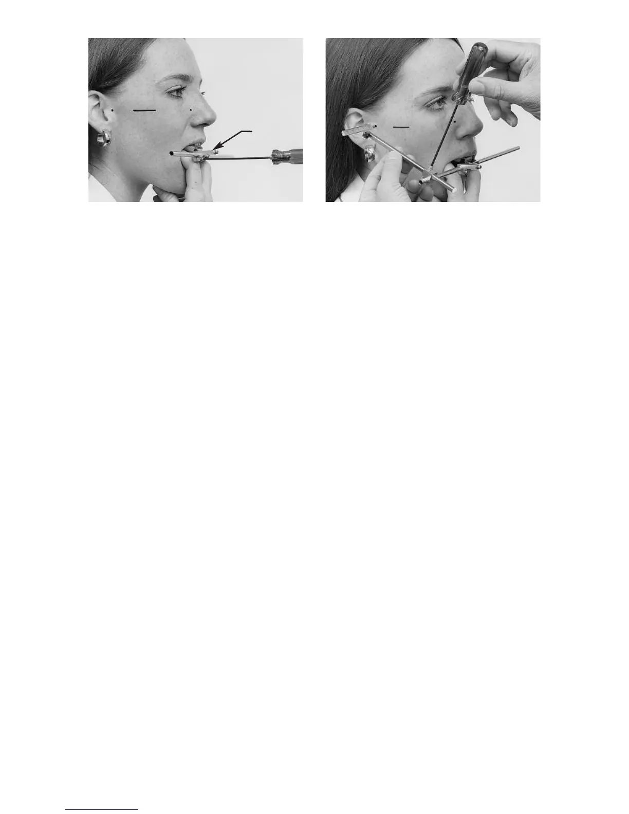
Insert the reference rod into its clamp
bringing it up from underneath the
clamp, with the step in the rod facing
toward the patient’s right (fig. 44). Hold
the reference plane locator between the
thumb and index finger of your left hand
so that you can read the instructions on
the back. The semilunar notch on the
locator’s inferior surface should be
placed over the bridge of the nose. Note
the small hole in the center of the loca-
tor. Turn the locator down flat so that the
instruction side faces downward and
index the hole on the locator over the
small dowel-like projection on the upper
extremity of the reference rod. Position
your eye approximately six inches in
front of the locator. By line of sight
adjust the locator by inclining it anterio-
posteriorly and medio-laterally until a
projection of its broad surfaces pass
through both posterior reference points
as indicated by the posterior reference
slides (fig. 45). At this time the anterior
reference point marked on the patient’s
face may be above or below the refer-
ence plane locator.
Adjust the height of the reference rod so
that a projection of the locator’s broad
fig. 42 fig. 43
Clamp