DAEnetIP2 v2 User Manual
21 Apr 2020
15. Appendix 9. Digital I/O ports (P3/P5)
This section describes how to use DAEnetIP2 v2 P3/P5 - 8 bit TTL IO port lines. They are not
buffered and you should very carefully otherwise the MCU could be damaged. They are
digital inputs/outputs. The output level voltage is “1” (3.3VDC) or “0” (0.25VDC) with consumption
< 1.5mA. All inputs/outputs have protection diodes to GND and +3.3VDC.
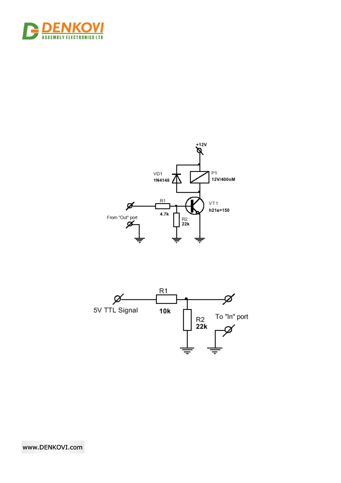
Below are given sample examples of I/O ports connections to external devices. The first figure
shows how to connect digital output to 12V relay. The second shows example for 5V TTL signal
input. R2 is recommend because sometimes the input signals are „tri-state”.
Figure 15.1. Connecting relay to digital output
Figure 15.2. Using digital I/O pin as input