SERVICE MANUAL
MODEL
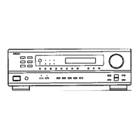
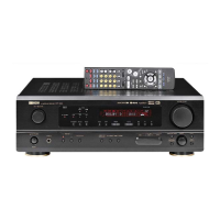
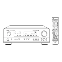
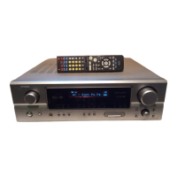
AVR-1604/684
AVC-1580
AV SURROUND RECEIVER / AMPLIFIER
16-11, YUSHIMA 3-CHOME, BUNKYO-KU, TOKYO 113-0034 JAPAN
X0174V.02 DE/CDM 0311
For U.S.A., Canada, Europe, U.K.,
Asia, China,Taiwan R.O.C., Korea
& Japan model
サービスをおこなう前に、このサービスマニュアルを
必ずお読みください。本機は、火災、感電、けがなど
に対する安全性を確保するために、さまざまな配慮を
おこなっており、また法的には「電気用品安全法」に
もとづき、所定の許可を得て製造されております。
従ってサービスをおこなう際は、これらの安全性が維
持されるよう、このサービスマニュアルに記載されて
いる注意事項を必ずお守りください。
本機の仕様は性能改良のため、予告なく変更する
ことがあります。
Please use this service manual with referring to the
operating instructions without fail.
Some illustrations using in this service manual are
slightly different from the actual set.
修理の際は、必ず取扱説明書を参照の上、作業を
行ってください。
本文中に使用しているイラストは、説明の都合上
現物と多少異なる場合があります。
補修用性能部品の保有期間は、製造打切後8年です。
注 意
For purposes of improvement, specifications and
design are subject to change without notice.