EasyManua.ls Logo

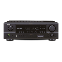
Denon AVR-1612 Service Manual

Denon AVR-1612
146 pages
To Next Page IconTo Next Page
Page #1 background imageLoading...
Page #1 background image
D&M Holdings Inc.
SERVICE MANUAL
e
e
MODEL JP E3 E2 EK EA E1 E1K E1C
AVR-1612
P P P P
AVR-1622
P
AV SURROUND RECEIVER
Ver. 1
S0233-1V01DM/DG1104
Some illustrations using in this service manual are slightly different from the actual set.
Please use this service manual with referring to the operating instructions without fail.
• For purposes of improvement, specications and design are subject to change without notice.

Table of Contents

Other manuals for Denon AVR-1612

Questions and Answers:

Denon AVR-1612 Specifications

General IconGeneral
Audio output channels5.1 channels
Audio A/D Converter (ADC)24-bit/96kHz
Power output per channel (1KHz@6 Ohm)120 W
Power output per channel (20-20KHz@8 Ohm)80 W
HDMI in4
Composite video in3
S-Video inputs quantity1
Speakers connectivity type-
Ethernet LANNo
Radio Data System (RDS)Yes
Preset stations quantity56
Analog signal format systemNTSC, PAL
DisplayLCD
HDMI version1.4
Product colorBlack
Audio decodersDolby Digital, Dolby Digital EX, Dolby Digital Plus, Dolby Pro Logic II, Dolby Pro Logic IIx, Dolby Pro Logic IIz, Dolby TrueHD, DTS 96/24, DTS Neo:6, DTS-ES, DTS-HD
Apple docking compatibilityiPod
Graphical user interface (GUI) languageEnglish, French, German
AC input voltage220-240 V
AC input frequency50 - 60 Hz
Power consumption (standby)0.5 W
Storage temperature (T-T)-10 - 60 °C
Operating temperature (T-T)0 - 40 °C
Storage relative humidity (H-H)5 - 90 %
Operating relative humidity (H-H)10 - 80 %
Weight and Dimensions IconWeight and Dimensions
Depth382 mm
Width435 mm
Height162 mm
Weight9200 g

Summary

Safety Precautions

Leakage Current Check

Check leakage current or line to chassis resistance before returning the set.

Cautions in Servicing and Inspection

Cautions for servicing, electric shock, disassembly, designated parts, and post-service checks.

Caution Concerning Important Safety Parts

Properties of electric and structural parts are critical; use designated part numbers.

Technical Specifications

Cautions in Servicing

Initializing AV Surround Receiver

Procedure for initializing the receiver when the microprocessor or Digital PWB is replaced.

Disassembly

Special Mode

Special Mode Setting Button

Details the button combinations to access various special modes.

1. µcom/DSP Version Display Mode

1.3. Error Display

2. Errors Checking Mode (Displaying the Protection History)

2.3. Clearing the Protection History

Warning Indication by the Power LED

4. Diagnostic Mode (Video/Audio (Signal) Path Confirmation Mode)

When the Microprocessor is Replaced with a New One

Procedure for Upgrading the Version of the Firmware

1.5. Communication Check

1.7. Complete the Firmware Updating

1.8. Notice

Adjustment

Audio Section

Adjusting the idling current for the audio section.

Surround Modes and Parameters

Surround

Trouble Shooting

1. Power

Troubleshooting steps for power-related issues.

1.2. Fuse is Blown

Steps to check and replace blown fuses.

2. Analog Video

A

B

3. HDMI/DVI

3.1. No Picture or Sound is Output

Troubleshooting flowchart for no picture or sound output from HDMI/DVI.

3.2. HDMI Test Point and Waveforms

4. Audio

4.1. Audio Check

Troubleshooting flowchart for audio output issues.

4.2. Power Amp (Main Unit)

4.3. Analog Audio

5. USB

5.1. USB Device is Not Recognized

Troubleshooting steps when a USB device is not recognized.

6. SMPS

Schematic Diagrams (1/16)

HDMI Part

Schematic diagrams for the HDMI part.

Schematic Diagrams (2/16)

Digital Supply Part

Schematic diagrams for the digital supply part.

Schematic Diagrams (3/16)

MCU Part

Schematic diagrams for the MCU part.

Schematic Diagrams (4/16)

MCU_Level_Chg Part

Schematic diagrams for the MCU level charge part.

Exploded View

Warning:

Critical parts indicated by a symbol require specific replacement parts.

Parts List of Exploded View

Semiconductors

1. IC's

Lists ICs with their functions and pin descriptions.

EX3AV Terminal Functions

Details terminal functions for the EX3AV IC.

ADV7623 (Digital : IC101)

Pin Function Descriptions

Details pin functions for the ADV7623 IC.

LC89058W-E (Digital : IC402)

ADSP21487KSWZ3B (Digital : IC404)

W9864G6JH-6 (Digital : IC405)

W9864G6JH-6 Pin Description

AK5358BET (Digital : IC451)

AK4358VQ (Digital : IC441)

R5F56108VNFP (Digital : IC201)

R2A15218FP (Input : IC404)

R2A15218FP Pin Function

TC4052BFT (Input : IC402,405)

Related product manuals