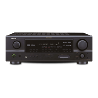
7
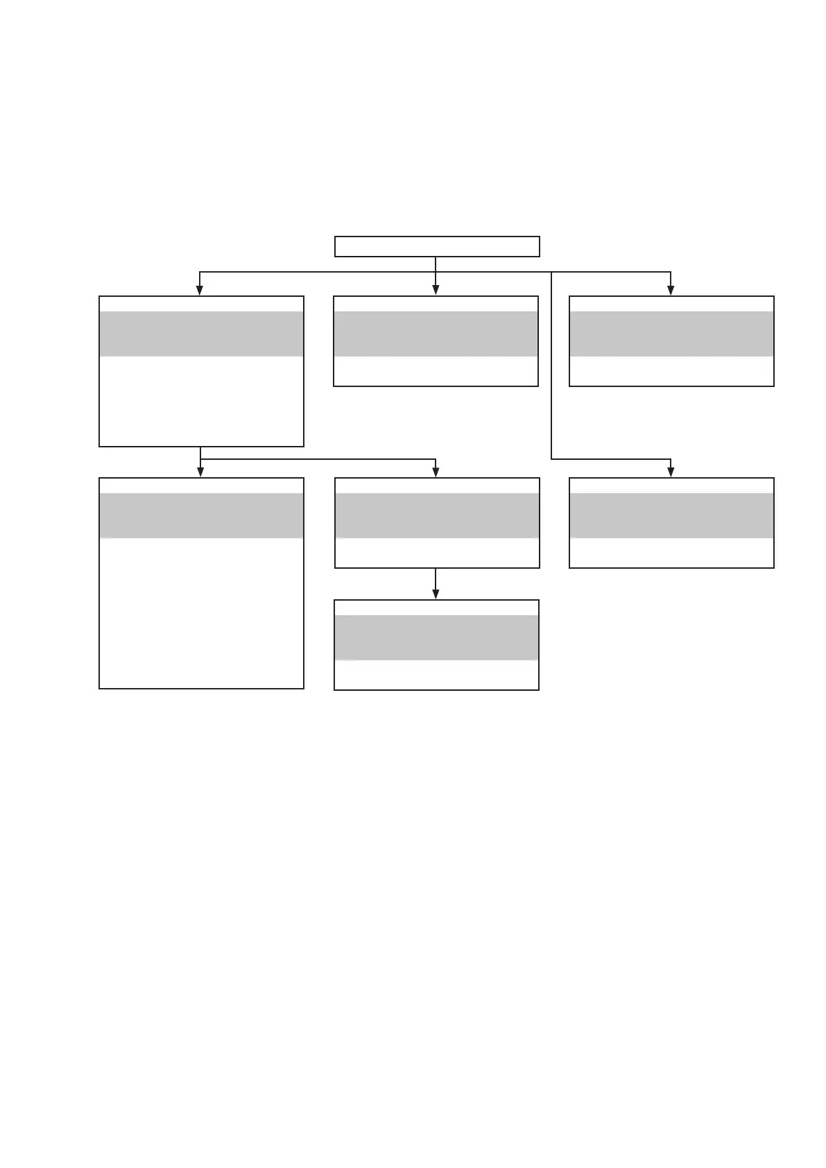
DISASSEMBLY
• Disassemble in order of the arrow in the following gure.
• In the case of the re-assembling, assemble it in order of the reverse of the following ow.
• In the case of the re-assembling, observe "attention of assembling".
• If wire bundles are untied or moved to perform adjustment or replace parts etc., be sure to rearrange them neatly as
they were originally bundled or placed afterward.
Otherwise, incorrect arrangement can be a cause of noise generation.
FRONT PANEL ASSY
Refer to "DISASSEMBLY
2. FRONT PANEL ASSY
and "EXPLODED VIEW"
HEADPHONE PCB
(Ref. No. of EXPLODED VIEW : C1)
USB PCB
(Ref. No. of EXPLODED VIEW : C2)
FRONT PCB
(Ref. No. of EXPLODED VIEW : C3)
VOLUME PCB
(Ref. No. of EXPLODED VIEW : C4)
WIRE SUPPORT PCB
(Ref. No. of EXPLODED VIEW : C7)
RADIATOR ASSY
Refer to "DISASSEMBLY
4. RADIATOR ASSY
and "EXPLODED VIEW"
MAIN PCB
(Ref. No. of EXPLODED VIEW : C10)
INPUT PCB ASSY
Refer to "DISASSEMBLY
3. INPUT PCB ASSY
and "EXPLODED VIEW"
INPUT PCB ASS'Y
(Ref. No. of EXPLODED VIEW : C11)
TRANS POWER
Refer to "DISASSEMBLY
7. TRANS POWER
and "EXPLODED VIEW"
TRANS POWER
(Ref. No. of EXPLODED VIEW : C9)
REGULATOR PCB
Refer to "DISASSEMBLY
5. REGULATOR PCB
and "EXPLODED VIEW"
REGULATOR PCB
(Ref. No. of EXPLODED VIEW : C6)
SMPS PCB
Refer to "DISASSEMBLY
6. PCB SMPS PCB
and "EXPLODED VIEW"
SMPS PCB
(Ref. No. of EXPLODED VIEW : C5)
HDMI UNIT ASSY
Refer to "DISASSEMBLY
1. HDMI UNIT ASSY
and "EXPLODED VIEW"
CONNECTOR PCB
(Ref. No. of EXPLODED VIEW : C13)
GND CONNECT PCB
(Ref. No. of EXPLODED VIEW : C17)
DIGITAL PCB ASS'Y
(Ref. No. of EXPLODED VIEW : C12)
TOP CABINET
 Loading...