27
AVR-5805/AVC-A1XV-UPGRADE
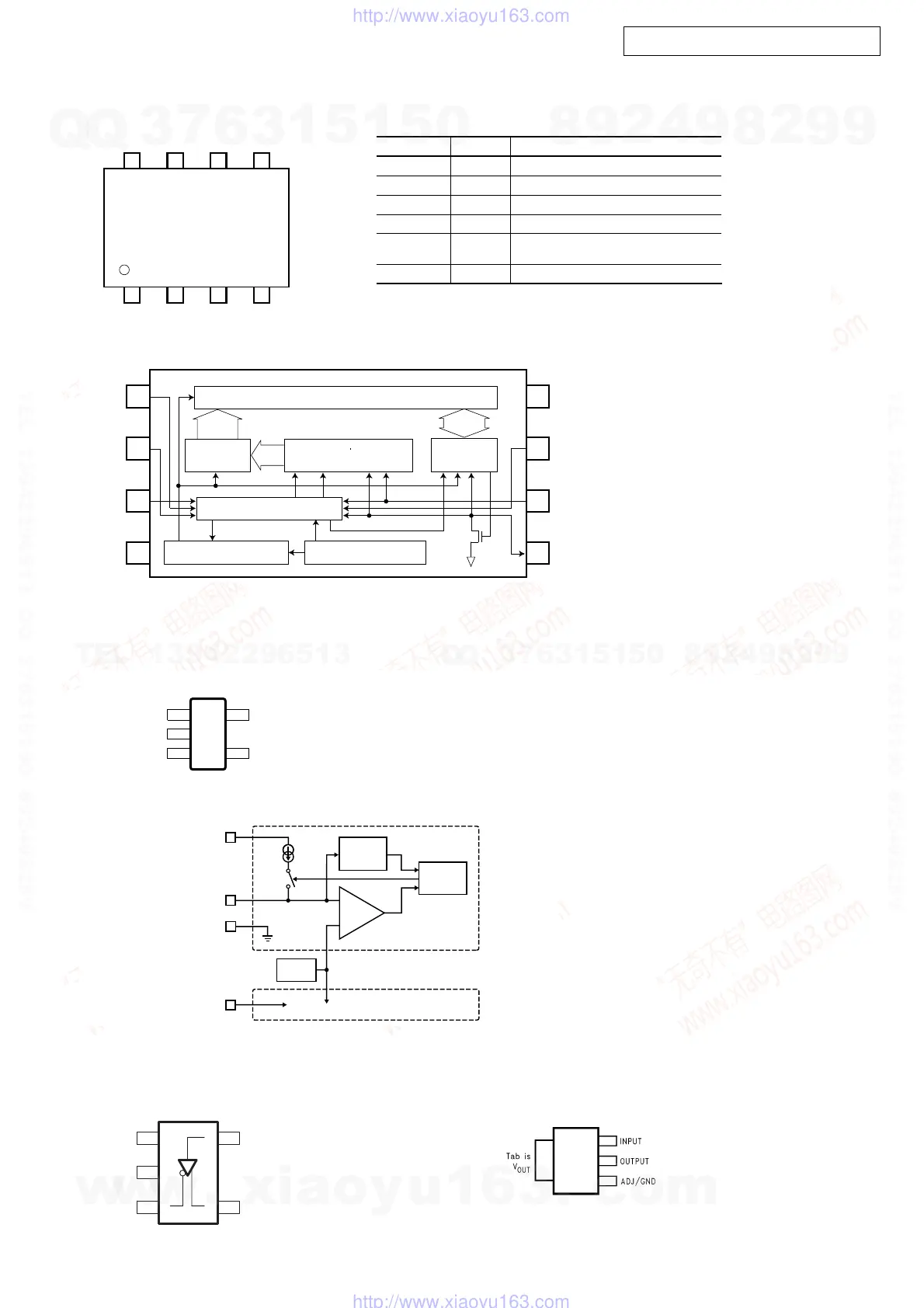
BR24L02F-WE2 (IC101, 102, 151, 152, 201, 202)
LTC1694CS5 (IC801, 803)
SN65LVDS1DBVR (IC456) LM1117MPX-1.8 (IC104, 154, 204, 302, 352, 502)
Block diagagram
1
A0
A1 2
A2 3
GND 4
V
CC
8
WP7
6SCL
SDA5
2kbit EEPROM array
Control logic
High voltage generator Vcc level detect
8bit
8bit
ACK
STOPSTART
Address
decoder
Slave word
address register
8bits
Data
register
Pinconfiguration
V
CC
A0
WP
A1
SCL
A2
SDA
GND
1234
5678
Pin name
Write protect input
Power supply
Function
Ground (0V)
Slave address set
Serial clock input
SDA
V
CC
A0, A1, A2
Pin name
GND
WP
SCL
I/O
IN
IN
IN
IN / OUT
Slave and word address,
serial data input, serial data output
*1 An open drain output requires a pull-up resistor.
*1
V
CC
1
GND 2
NC 3
5 SMBus1
4 SMBus2
TOP VIEW
PI N FUNCTIONS
V
CC
(Pin 1): Power Supply Input. V
CC
can range from 2.7V
to 6V and requires a 0.1
F bypass capacitor to GND.
Supply current is typically 45
A when the SMBus or I
2
C
lines are inactive (SCL and SDA are a logic high level).
GND (Pin 2):Ground.
NC (Pin 3):No Connection.
SMBus2 (Pin 4):Active Pull-Up for SMBus.
SMBus1 (Pin 5):Active Pull-Up for SMBus.
μ
μ
BLOCK DIAGRA
M
-
+
SLEW RATE
DETECTOR
CONTROL
LOGIC
0.65V
V
REF
VOLTAGE
COMP
2.2mA
CHANNEL ONE
CHANNEL TWO
(DUPLICATE OF CHANNEL ONE)
1
V
CC
5
SMBus1
SMBus2
2
GND
4
3
2
4
5
1
V
CC
GND
Z
D
Y
w
w
w
.
x
i
a
o
y
u
1
6
3
.
c
o
m
Q
Q
3
7
6
3
1
5
1
5
0
9
9
2
8
9
4
2
9
8
T
E
L
1
3
9
4
2
2
9
6
5
1
3
9
9
2
8
9
4
2
9
8
0
5
1
5
1
3
6
7
3
Q
Q
TEL 13942296513 QQ 376315150 892498299
TEL 13942296513 QQ 376315150 892498299
http://www.xiaoyu163.com
http://www.xiaoyu163.com
 Loading...