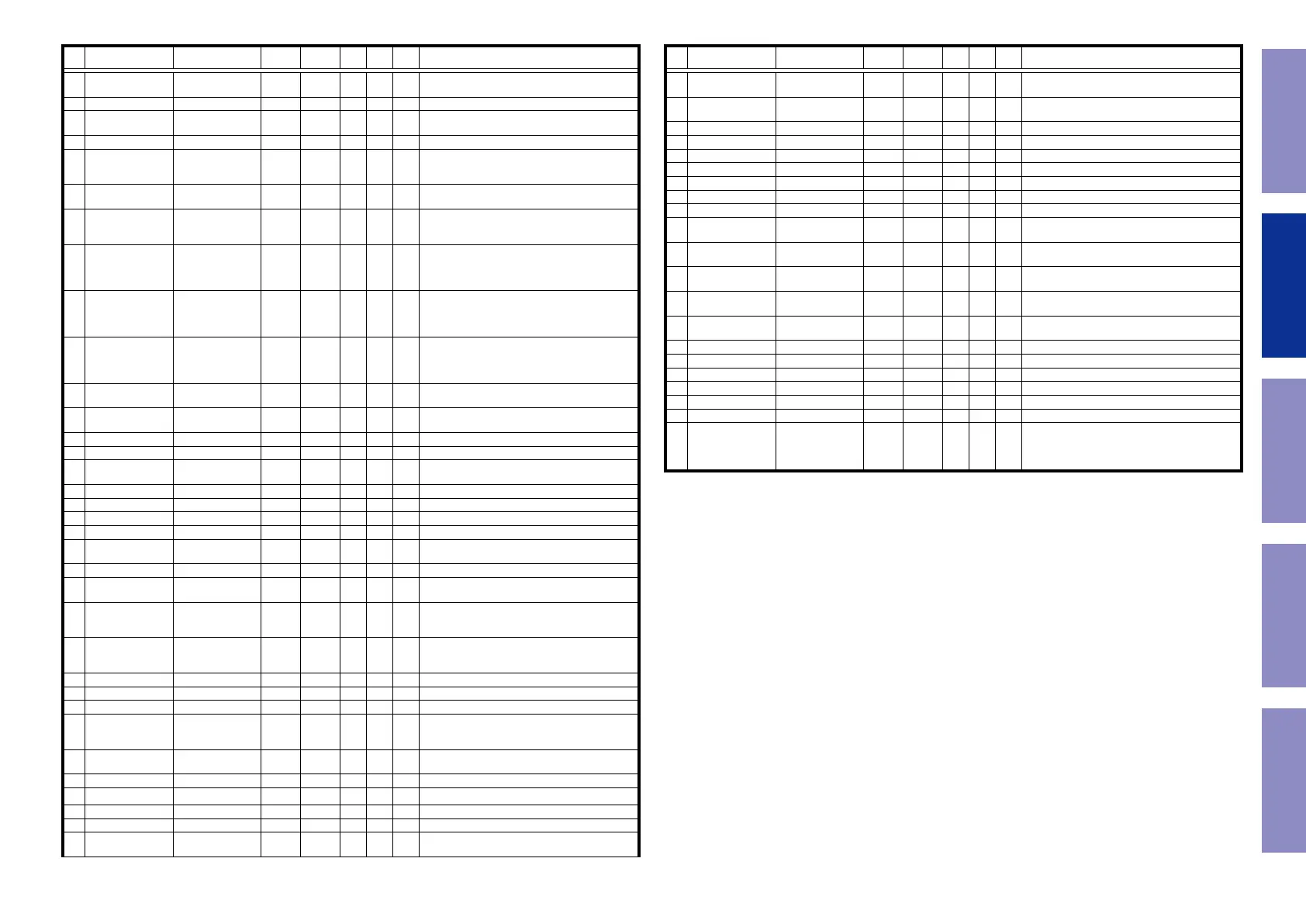
Pin Pin Name Symbol I/O Pu/Pd STBY STOP
CEC
STBY
Function
90
P70/CS3#-B/
ADTRG2#
DIR RST O L L L DIR (PCM9211) control pin
91 VCC VCC - - - - Power supply pin.
92
PB0/A8/PO24/
TIOCA9
7623 ROM HOLD O L L L Flash ROM for GUI control pin
93 VSS VSS - - - - Ground pin.
94
PA7/A7/PO23/
TIOCA8/TIOCB8/
TCLKH
VEXP OE O L L L Expander (MC14094) control pin
95
PA6/A6/PO22/
TIOCA8
VSEL A I I I I Master volume (Rotary encoder) signal input pin
96
PA5/A5/PO21/
TIOCA7/TIOCB7/
TCLKG
VSEL B I I I I Master volume (Rotary encoder) signal input pin
97
PA4/A4/PO20/
TIOCA7
ZVOL
DATA(X1300(NA)/
NC(X1300(AP/CH)/
S720)
O L L L ZONE volume(BD3812) control pin
98
PA3/A3/PO19/
TIOCC6/TIOCD6/
TCLKF
ZVOL
CLK(X1300(NA)/
NC(X1300(AP/CH)/
S720)
O L L L ZONE volume(BD3812) control pin
99
PA2/A2/PO18/
TIOCC6/TCLKE
PRE Z2
MUTE(X1300(NA)/
NC(X1300(AP/CH)/
S720)
O L L L ZONE volume(BD3812) control pin
100
PA1/A1/PO17/
TIOCA6/TIOCB6
CLK MUTE O L L L
Audio PLD (5M80ZT100C5N) control pin(for MUTE
CLK.When mute is active,set to High)
101
PA0/A0/BC0#/
PO16/TIOCA6
PRE MUTE O L L L MUTE for preout control pin
102 PE7/IRQ7-A/D15 DSP FLAG3 I Pd L L L DSP(CS49844A) interrupt signal input pin
103 PE6/IRQ6-A/D14 MN864788 HINT I I I I HDMI Tx (MN864788) interrupt signal input pin
104 PE5/IRQ5-A/D13 MN864788 HAINT I I I I
HDMI Tx (MN864788) interrupt signal input pin(for
Audio)
105 PE4/D12 ISEL A I I I I Input selector (Rotary encoder) signal input pin
106 PE3/D11 ISEL B I I I I Input selector (Rotary encoder) signal input pin
107 PE2/D10 VOL CLK O L L L Input selecter w/ Volume(NJU72340A) control pin
108 PE1/D9 VOL DATA O L L L Input selecter w/ Vvolume(NJU72340A) control pin
109 PE0/D8 PLD WRITE O L L L
PLD writing control(To switch the PLD and JTAG I/
F.When writing,set to Low)
110 PD7/D7 JTAG TDO I L L L JTAG I/F for PLD writing
111 PD6/D6 JTAG TMS/APLD CS O/O L L L
JTAG I/F for PLD writing/Audio PLD
(5M80ZT100C5N) control pin
112 PD5/D5
JTAG TDI/APLD
DATA/DAC DATA
O/O L L L
JTAG I/F for PLD writing/Audio PLD
(5M80ZT100C5N) control pin/DAC (PCM1690)
control pin
113 PD4/D4
JTAG TCK/APLD
CLK/DAC CLK
O/O L L L
JTAG I/F for PLD writing/Audio PLD
(5M80ZT100C5N) control pin/DAC (PCM1690)
control pin
114 P64/CS4#-B VEXP STB O L L L Expander (MC14094) control pin
115 P63/CS3#-A/CS7#-A THERMAL A I SW3VPu I L I Protection detect signal input pin
116 P62/CS2#-A/CS6#-A E SPI CS O N3VPu L L L Ethernet(CY920) control pin
117
P61/CS1#/CS2#-
B/CS5#-A/CS6#-B/
CS7#-B
DAC MS O L L L DAC (PCM1690) control pin
118
P60/CS0#/CS4#-A/
CS5#-B
DAC RST O L L L DAC (PCM1690) control pin
119 PD3/D3 VEXP CLK O L L L Expander (MC14094) control pin
120 PD2/D2 VEXP DATA O L L L Expander (MC14094) control pin
121 PD1/D1 FL CLK O L L L FL display control pin
122 PD0/D0 FL DATA O L L L FL display control pin
123 P97/AN15 DA POWER O L L L
Digital audio power supply (DA3.3V,DA1.2V) control
pin
Pin Pin Name Symbol I/O Pu/Pd STBY STOP
CEC
STBY
Function
124 P96/AN14 CEC POWER O L L -
CEC standby power supply
control(CEC5V,CEC3.3V,CEC1.8V)
125 P95/AN13 DV POWER1 O L L -
Digital video power supply (DV5V,DV3.3V) control
pin
126 P94/AN12 THERMAL B I SW3VPu I L I Protection detect signal input pin
127 P93/AN11 MAIN POWER O L L L Power supply control pin
128 P92/AN10 CPU POWER O L L L CPU power supply control pin
129 P91/AN9 AMPSIGDET I I L I Signal level monitor pin (AD converter)
130 VSS VSS - - - - Ground pin
131 P90/AN8 MODE I I I I Region setting pin
132 VCC VCC - - - - Power supply pin
133 P47/IRQ15-B/AN7 DC DET/ASO I I I I
Protection detect signal input pin (for DC and ASO)
(A/D converter)
134 P46/IRQ14-B/AN6 H/P DET / MIC DET I I I I
Headphone insert detect pin/Microphone insert
detect pin (A/D converter)
135 P45/IRQ13-B/AN5 KEY3 I SW3VPu I I I
Key control signalinput pin (When standby
mode,set to inturrupt)
136 P44/IRQ12-B/AN4 KEY2 I SW3VPu I I I
Key control signalinput pin (When standby
mode,set to inturrupt)
137 P43/IRQ11-B/AN3 KEY1 I SW3VPu I I I
Key control signalinput pin (When standby
mode,set to inturrupt)
138 P42/IRQ10-B/AN2 E SPI REQ I Pd I L I Ethernet(CY920) control pin
139 P41/IRQ9-B/AN1 CURRENT DET I I L I Current level monitor pin (A/D converter)
140 AVSS AVSS - - - - Ground pin
141 P40/IRQ8-B/AN0 CEC_IN I SW3VPu I I I CEC-D control pin
142 VREF VREF - - - - Reference power supply pin
143 AVCC AVCC - - - - Analog power supply pin
144
P05/IRQ13-A/
TMO3/RxD4/TCK
TCK/RXD MITSUBI-
SHI/NC(NORMRAL)
I/I/I M3VPu -/-/I -/-/I I
E20 Emulator control pin/Mitsubishi writter control
pin/When Normal Operating Mode,set to input.
44
Caution in
servicing
Electrical Mechanical Repair Information Updating
 Loading...