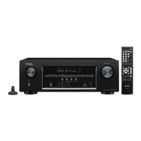
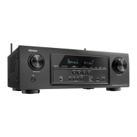
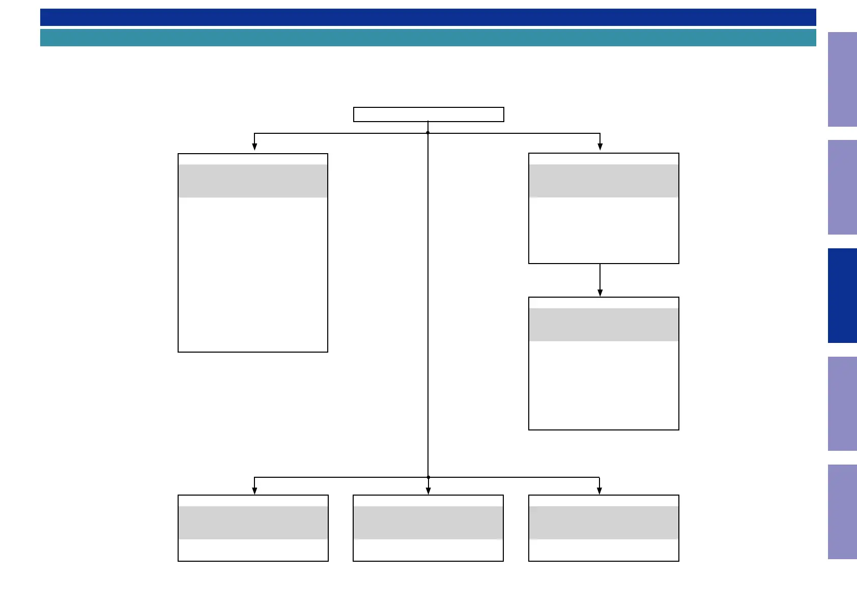
DISASSEMBLY
Flowchart
• Remove each part following the ow below.
• Reassemble the removed parts in the reverse order.
• Read "SAFETY PRECAUTIONS" before reassembling the removed parts.
• If wire bundles are removed or moved during adjustment or part replacement, reshape the wires after completing the work. Failure to shape the wires correctly may cause problems such as noise.
• See EXPLODED VIEW
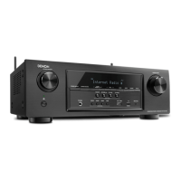
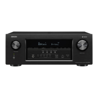
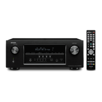
FRONT PANEL ASSY
See "DISASSEMBLY"
1. FRONT PANEL ASSY
and "EXPLODED VIEW"
FRONT PCB
Ref. No. of EXPLODED VIEW : P 1
ENCODER&POWER PCB
Ref. No. of EXPLODED VIEW : P 2
HEADPHONE PCB
Ref. No. of EXPLODED VIEW : P 3
iPODUSB_MIC PCB
Ref. No. of EXPLODED VIEW : P 4
F-HDMI PCB
Ref. No. of EXPLODED VIEW : P 5
HDMI CABLE GUIDE PCB
Ref. No. of EXPLODED VIEW : P 7
FRONT CABLE GUIDE PCB
Ref. No. of EXPLODED VIEW : P 8
TOP COVER
REGULATOR PCB
See "DISASSEMBLY"
5. REGULATOR PCB
and "EXPLODED VIEW"
REGULATOR PCB
Ref. No. of EXPLODED VIEW : P 11
RADIATOR ASSY
See "DISASSEMBLY"
3. RADIATOR ASSY
and "EXPLODED VIEW"
MAIN PCB
Ref. No. of EXPLODED VIEW : P 6
BIAS TR PCB
Ref. No. of EXPLODED VIEW : P 9
DIFF AMP PCB
Ref. No. of EXPLODED VIEW : P 12
PHONE WIRE GUIDE PCB
Ref. No. of EXPLODED VIEW : P 19
DIGITAL PCB ASSY
See "DISASSEMBLY"
2. DIGITAL PCB ASSY
and "EXPLODED VIEW"
DIGITAL PCB
Ref. No. of EXPLODED VIEW : P 13
CY920, MODULE
Ref. No. of EXPLODED VIEW : P 14
TUNER PCB
Ref. No. of EXPLODED VIEW : P 15
TRANS POWER
See "DISASSEMBLY"
6. TRANS POWER
and "EXPLODED VIEW"
TRANS POWER
Ref. No. of EXPLODED VIEW : P 16
POWER PCB
See "DISASSEMBLY"
4. SMPS PCB
and "EXPLODED VIEW"
SMPS PCB
Ref. No. of EXPLODED VIEW : P 10
55
Caution in
servicing
Electrical Mechanical Repair Information Updating
 Loading...