Explanatory Photos for DISASSEMBLY
• For the shooting direction of each photos used in this manual, see the photo below.
• A, B, C and D in the photo below indicate the shooting directions of photos.
• The photographs with no shooting direction indicated were taken from the top of the unit.
• Photos of AVR-X6300H E3 are used in this manual.
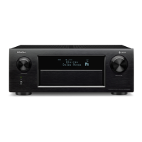
The viewpoint of each photograph
(Shooting direction : X) [View from the top]
↑Shooting direction: A↑
↓Shooting direction: B↓
↓Shooting direction: D↓
↑Shooting direction: C↑
↑
Front side
↑
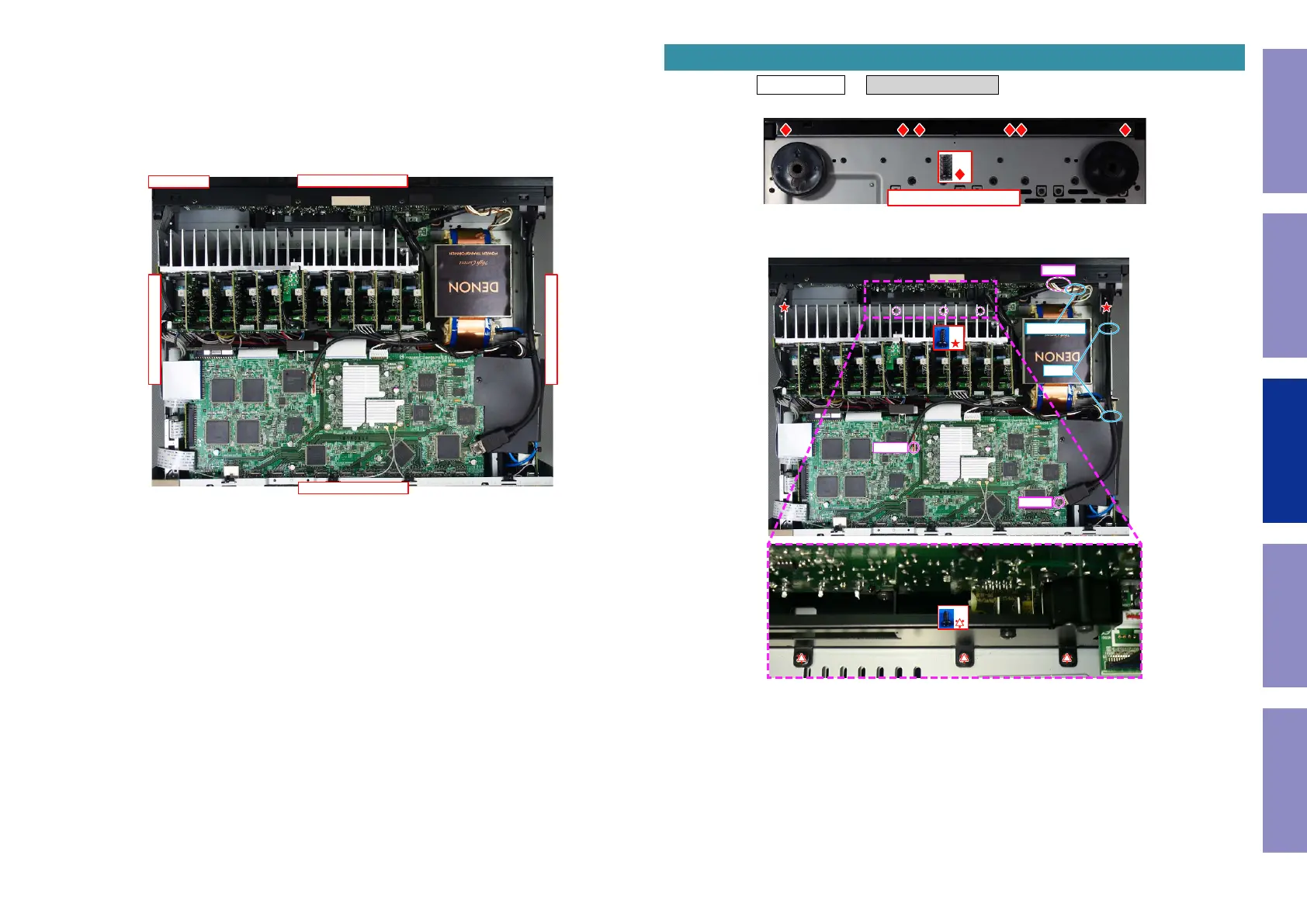
Proceeding : TOP COVER → FRONT PANEL ASSY
(1) Remove the screws.
(2) Remove the screws. Cut the wire clamp, then remove the STYLE PIN and connector.
1. FRONT PANEL ASSY
View from the bottom
x6
x3
x2
N6401
N3403
N8001
CUT
STYLE PIN
72
Caution in
servicing
Electrical Mechanical Repair Information Updating
 Loading...