EasyManua.ls Logo

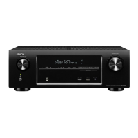
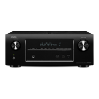
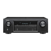
Denon AVR-X1400H Service Manual

Denon AVR-X1400H
148 pages
To Next Page IconTo Next Page
Page #1 background imageLoading...
Page #1 background image
START::|sX3k6VQNaf/6VbQg1Aav9Q==|/sZuq44af05SNClwHgwKDXU+EbMOZV++PyXfRl9edUU=|XOIUVeyoWOE5XcWqSdEcbA==|::END
INTEGRATED NETWORK AV RECEIVER
AVR-X1400H
AVR-S730H
Service Manual
Click here!
On-line service parts list
URL:http://dmedia.dmglobal.com/Document/DocumentDetails/23150
Online Parts List (P5 to P7)
On-line owner’s manual
NA: http://manuals.denon.com/AVRX1400H/NA/EN/index.php
EU: http://manuals.denon.com/AVRX1400H/EU/EN/index.php
AP: http://manuals.denon.com/AVRX1400H/AP/ZH/index.php
NA: http://manuals.denon.com/AVRS730H/NA/EN/index.php
CAUTION IN SERVICING
ELECTRICAL
MECHANICAL
REPAIR INFORMATION
UPDATING
Ver. 2
Please refer to the MODIFICATION NOTICE.
purposesofimprovement,specicationsanddesignaresubjecttochangewithoutnotice.
•Pleaseusethisservicemanualwithreferringtotheoperatinginstructionswithoutfail.
•Someillustrationsusinginthisservicemanualareslightlydifferentfromtheactualset.

Table of Contents

Other manuals for Denon AVR-X1400H

Question and Answer IconNeed help?

Do you have a question about the Denon AVR-X1400H and is the answer not in the manual?

Denon AVR-X1400H Specifications

General IconGeneral
Receiver typeSurround
Frequency range20 - 20000 Hz
Pre-out channels2 SW
Input sensitivity200 mV
Pre-out connectivityYes
Audio output channels7.2 channels
Signal-to-Noise Ratio (SNR)98 dB
Total Harmonic Distortion (THD)0.08 %
Power output per channel (1KHz@6 Ohm)145 W
Power output per channel (20-20KHz@8 Ohm)80 W
HDMI in6
Digital audio coaxial in0
Ethernet LAN (RJ-45) ports1
Multichannel audio input typeRCA
Component video (YPbPr/YCbCr) in2
Headphone connectivity3.5 mm
Connectivity technologyWired & Wireless
Speakers connectivity type3.5mm
Audio formats supportedALAC, DSD, FLAC, MP3, WAV
DisplayVFL
HDCP version2.2
Apple dockingNo
Product colorBlack
Audio decodersDTS-HD Master Audio, DTS:X, Dolby Atmos, Dolby Surround
Volume controlRotary
Center speaker impedance16 Ω
AM band range522 - 1611 kHz
FM band range87.5 - 108 MHz
Supported radio bandsAM, FM
Internet radio services supportedDeezer, Napster, Pandora, SIRIUS Internet Radio, Spotify, Tidal, iHeartRadio
AC input voltage230 V
AC input frequency50 Hz
Power consumption (standby)0.1 W
Power consumption (typical)430 W
Supported video modes720i, 720p, 960p, 1080i, 1080p, 2160p
Supported graphics resolutions3840 x 2160
CertificationCE, EAC
Weight and Dimensions IconWeight and Dimensions
Depth339 mm
Width434 mm
Height151 mm
Weight8500 g

Summary

CAUTION IN SERVICING

Safety Precautions

Essential safety guidelines to follow during servicing.

Unit Initialization and Servicing Jigs

Cautions for unit initialization and servicing jigs for AVR-X1400H/S730H.

Handling Sensitive Components

Guidelines for safely handling semiconductors and optical units.

SAFETY PRECAUTIONS

Leakage Current Check and Safety Checks

Procedures for leakage current and post-service safety checks.

Servicing Cautions and Important Parts

General cautions for servicing, electric shock, and critical safety parts.

NOTES FOR SCHEMATIC AND PARTS LIST

Instructions for Handling Semiconductors and Optical Unit

Procedures for grounding human body and workbench for static discharge.

ONLINE PARTS LIST

ONLINE PARTS LIST SEARCH

BLOCK DIAGRAM

DIGITAL AUDIO DIAGRAM

VIDEO DIAGRAM

POWER DIAGRAM

VCC Diagram

Diagram showing the power supply distribution and current consumption.

MECHANICAL

Disassembly Overview

Section covering disassembly, exploded view, and packing view.

DISASSEMBLY

Disassembly Flowchart

Step-by-step flowchart for disassembling the unit.

DISASSEMBLY PROCEDURES

Front Panel Assy Disassembly

Detailed steps and photos for disassembling the front panel assembly.

EXPLODED VIEW

AVR-S730H/X1400H Exploded View

Exploded view showing all parts of the AVR-S730H/X1400H.

REPAIR INFORMATION

Troubleshooting and Failure Analysis

Guide to diagnosing and resolving common operational problems and failures.

TROUBLE SHOOTING

1. Power: Unit Does Not Power On

Troubleshooting steps for power-related issues, including fuse checks.

2. Analog Video

3. HDMI/DVI

3.1. No Picture or Sound Output (HDMI to HDMI)

Troubleshooting guide for no video or audio output over HDMI.

4. AUDIO

4.1. Audio Check

Steps to check audio output for various input sources and modes.

4.2. Power AMP (AMP PCB)

No Audio Output / Protection Activated

Troubleshooting steps for no audio output with protection activated.

4.3. Analog Audio

5. Network / Bluetooth / USB

5.1. Cannot Connect to the Network

Troubleshooting steps to resolve network connectivity issues.

5. Network / Bluetooth / USB (Continuation)

5.2. Cannot Establish a Bluetooth Connection

Troubleshooting steps for Bluetooth connection problems.

5.3. Cannot Recognize Connected USB Device

Steps to troubleshoot issues with recognizing connected USB devices.

6. SMPS

DC 5V Output Not Working

Troubleshooting steps when DC 5V is not output from the SMPS.

HDMI "Rx/Tx" Failure Detection

1. Prior Checking

Initial check for HDMI connector condition and pin deformation.

3. Starting Detecting the Point of Failure

(1) Start in HDMI Diagnostics Mode

How to enter HDMI Diagnostics mode.

Error Code Display Interpretation

Interpreting error codes displayed during HDMI diagnostics.

3-1. Error Code H1-01 Failure Detection Procedure

Checking Device (HDMI Rx/Tx)

Procedure for detecting failures related to HDMI Rx/Tx IC.

3-2. Error Code H1-02 Failure Detection Procedure

Checking Device (HDMI SW)

Procedure for detecting failures related to HDMI SW IC.

3-3. Error Code H1-07 Failure Detection Procedure

Checking Device (OSD)

Procedure for detecting failures related to OSD IC.

3-4. Error Code H1-15 Failure Detection Procedure

Checking Device [IC732 : MX25L3206EMI(E3, E1C, K)/MX25L6406EMI(E2)]

Procedure for detecting failures related to the OSD ROM IC.

3-5. Error Code H1-08 Failure Detection Procedure

Checking Device [IC781 : CS49844A]

Procedure for detecting failures related to the DSP IC.

3-6. Error Code H1-12 Failure Detection Procedure

Checking Device [IC761 : PCM9211]

Procedure for detecting failures related to the DIR IC.

3-7. HDMI Rx/Tx [MN864788] & OSD[ADV7623] Failure Detection Procedure

Checking Operation Between HDMI (Rx/Tx) and Player

Steps to check HDMI operation between the unit and player.

Checking +5V/DDC Status Register (HDMI Rx/Tx)

Checking +5V/DDC status for HDMI Rx/Tx.

3-8. HDMI SW [MN864787] Failure Detection Procedure

Checking Operation Between HDMI (HDMI SW) and Player

Steps to check HDMI SW operation between the unit and player.

Checking +5V/DDC Status Register (HDMI SW)

Checking +5V/DDC status for HDMI SW.

3-9. Front HDMI Buffer IC [AD8195] Failure Detection Procedure

Checking Operation Between HDMI (Front HDMI Buffer) and Player

Steps to check Front HDMI Buffer operation.

Checking +5V/DDC Status Register (Front HDMI Buffer)

Checking +5V/DDC status for Front HDMI Buffer.

3-10. OSD [ADV7623] Failure Detection Procedure

Checking the TMDS Status Register (OSD -> HDMI Rx/Tx)

Checking TMDS status for OSD to HDMI Rx/Tx communication.

Checking HPD/RXSENSE Status Register (HDMI TX -> Monitor)

3-11. HDMI Rx/Tx [MN864788] & OSD[ADV7623] Failure Detection Procedure

Checking the TMDS Status Register (Rx/Tx -> OSD)

Checking TMDS status for HDMI Rx/Tx to OSD communication.

CLOCK FLOW & WAVEFORM IN DIGITAL BLOCK

SPECIAL MODE

1.4. Error Display

Error Code Descriptions and Countermeasures

Table detailing error codes, states, and display messages.

2. PANEL / REMOTE LOCK Selection Mode

3. Selecting the Mode for Service-related

3-1.1. Actions, 3-1.2. Starting up, 3-1.3. Displaying and Selecting Each Mode

Actions, startup, and display/selection for service modes.

3-2. Protection History Display Mode

3-2.1. Actions, 3-2.2. Starting up, 3-2.3. Protection Information and Displays

Actions, startup, and information display for protection history.

Protection History Display Mode (Continuation)

3-2.4. Clearing the Protection History

Two methods to clear the protection history.

3-3. Operation Info Mode

3-5. Remote ID Setup Mode

4. Protection Pass Mode

5. Network Initialization Mode

6. Clearing the Operation Info

DIAGNOSTIC MODE

DIAGNOSTIC PATH DIAGRAM

ANALOG AUDIO DIAGRAM

JIG FOR SERVICING

ADJUSTMENT

UPDATING

Firmware Update Procedure

General steps for updating firmware.

PCB REPLACEMENT PROCEDURES

FIRMWARE UPDATE PROCEDURE

USB FLASH DRIVE UPDATE PREPARATION

USB FLASH DRIVE UPDATE METHOD

3.2. Start the Update

Steps to initiate the firmware update process.

SERVICE REGION SETTINGS UPDATE

NORMAL FIRMWARE UPDATE METHOD FROM USB FLASH DRIVE

5.2. Start Normal Update

Steps to initiate a normal firmware update via USB.

NORMAL FIRMWARE UPDATE METHOD FROM OTA

ERROR CODE INFORMATION

Related product manuals