ADJUSTMENT
F Rch S Rch C Rch S Lch F Lch S Back Rch S Back Lch
VR550 VR540 VR530 VR520 VR510 VR570 VR560
SBRSBL
SL SR
CEN
FL
FR
CN550 CN540 CN530 CN520 CN510 CN570 CN560
DC Voltmeter
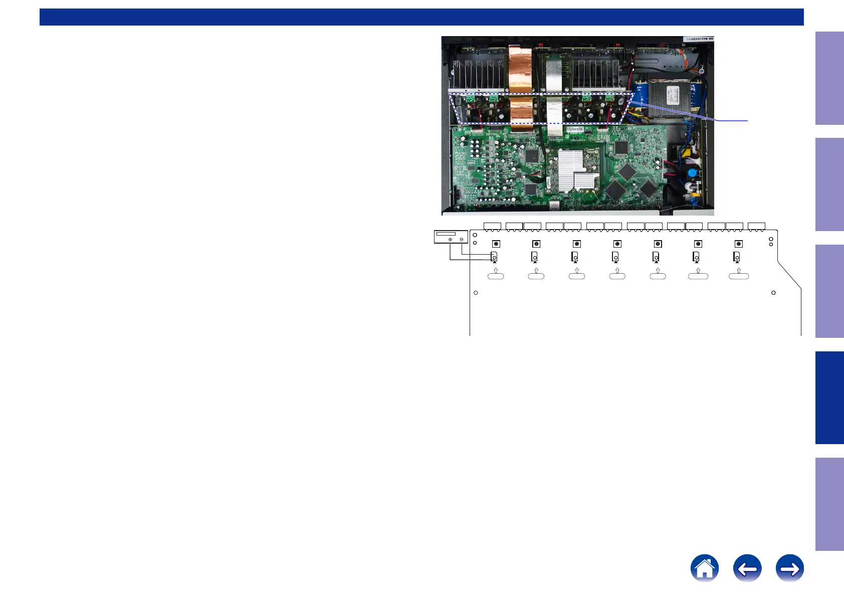
AMP UNIT
Adjusting Idling Current
1. Preparation
(1) Prepare a DC voltmeter.
(2) Place the unit under normal usage conditions, away from highly ventilated areas such as next to an
air conditioning machine or electric fan.
The set requires an ambient temperature of 15℃ to 30℃ and standard humidity.
(3) Settings of This Unit
• POWER (Power source switch) STANDBY
• SPEAKER (Speaker terminal) No load
(Do not connect equipment such as speakers or dummy resistors.)
2. Adjustment Procedure
(1) Remove the top cover and turn VR510( (ALL Channel) of the MAIN PCB counterclockwise(
c
) as far
as possible.
(2) Connect the DC Voltmeter to the test points.
FRONT-Lch : CN510 : VR510
FRONT-Rch : CN550 : VR550
CENTER ch : CN530 : VR530
SURROUND-Lch : CN520 : VR520
SURROUND-Rch : CN540 : VR540
SURROUND-BACK Lch : CN560 : VR560
SURROUND-BACK Rch : CN570 : VR570
(3) Connect the power cord to an outlet. Next, press the power button to turn on the power.
(4) Set this unit as follows.
MASTER VOLUME : "---" (
c
min.) : turn counterclockwise to the lowest position.
SPEAKER (Speaker terminal) : No load
(Do not connect equipment such as speakers or dummy resistors.)
MODE : MCH STEREO
FUNCTION : DVD
(5) Turn VR510 clockwise (
x
) and adjust the voltage of the test point to "
2.0mV ± 0.5mV DC
" within 2
minutes.
(6) Check whether the voltage is within the range "
2.0mV +2mV/-1mV DC
" 10 minutes after adjust-
ment.
(7) Adjust the variable resistance of each channel using the same method.
138
Caution in
servicing
Electrical Mechanical Repair Information Updating

 Loading...