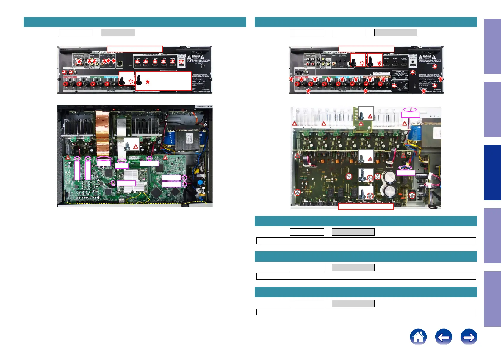
Proceeding : TOP COVER → DIGITAL PCB
(1) Remove the screws.
(2) Remove the screws. Remove the FFC. Remove the connector.
2. DIGITAL PCB
↓Shooting direction: A↓
x6
x7 X1400H E3 Only
x8
x2
FFC
FFC
CN813
CN741
CN823
CN754
CN822
CN753
Proceeding : TOP COVER → DIGITAL PCB → RADIATOR ASSY
(1) Remove the screws.
(2) Remove the screws. Remove the connector.
Proceeding : TOP COVER → SMPS PCB
See "EXPLODED VIEW" for instructions on removing the SMPS PCB.
Proceeding : TOP COVER → REGULATOR PCB
See "EXPLODED VIEW" for instructions on removing the REGULATOR PCB.
Proceeding : TOP COVER → POWER TRANS
See "EXPLODED VIEW" for instructions on removing the transformer (TRANS).
3. RADIATOR ASSY
↓Shooting direction: A↓
x12x4
↑Shooting direction: A↑
x4
x2
x2
x2
CN502
CN104
4. SMPS PCB
5. REGULATOR PCB
6. POWER TRANS
61
Caution in
servicing
Electrical Mechanical Repair Information Updating

 Loading...