6.4.1. Abnormality in TUNER
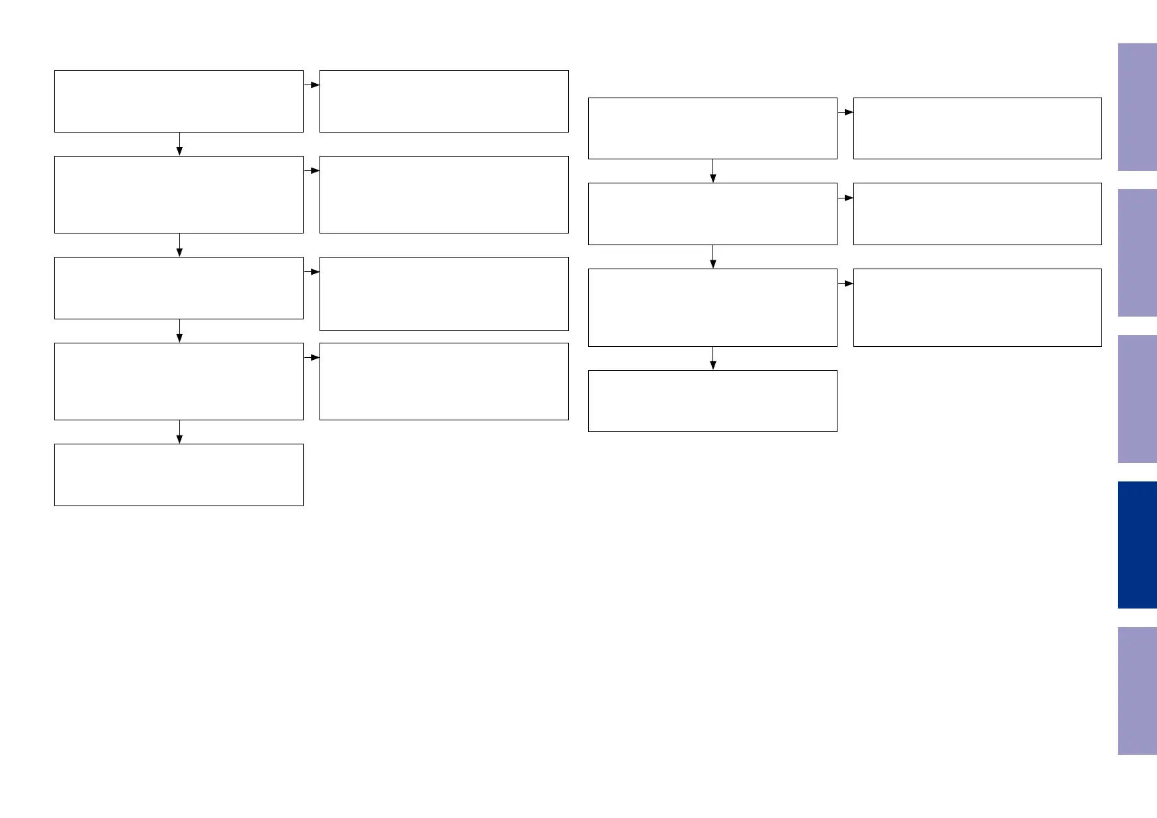
6.4. Abnormality in specic source6.3. No sound is output from inputs except DIGITAL IN
Check the audio line of the [U8] output
MAIN PCB
[U8 : 7, 8pin] → [U17 : 1, 12pin]
Check the audio signal line
Check I2S between [U5 : SPHE8104] and [U19 :
STA339BW]
MAIN PCB
[R250, R365, R366, R367]
I2S is input as normal to [U19]
Check of Control Data.
MAIN PCB [U8 : 3, 4pin]
Control data is input as normal to [U8 : 3, 4pin]
Check the audio signal output of the function
selector
MAIN PCB
[U17 : 3, 13pin]
Audio signal is output to [U17 : 3, 13pin]
No sound is output from the TUNER input source
No sound is output from the TUNER, ANALOG IN
and BLUETOOTH inputs
Check the following parts and surrounding
circuits
MAIN PCB
[U19]
Check the Audio output.
MAIN PCB [U8 : 7, 8pin]
Audio signal is output as normal to [U8 : 7, 8pin]
when TUNER receives a station
Check the I2S signal output of the ADC
MAIN PCB
[U16 : 9, 10, 11, 12pin]
I2S signal is output as normal from [U16]
Check the following parts and surrounding
circuits
MAIN PCB
[U5]
MAIN PCB
Check the data line from [U5 : 119, 120pin] to [U8
: 3, 4pin].
Check the state / soldering for the following
parts.
MAIN PCB
[U17]
Check the surrounding circuits.
Go to "6.4.2. Abnormality in BLUETOOTH"
No issues in circuits after Function SEL.
Go to "6.4. Abnormality in specic source"
Check the circuits around [U8]. If there are no
abnormalities, there may be a defect in [U8].
(Replace [U8].)
Check the state / soldering for the following
parts.
MAIN PCB
[U16]
Check the surrounding circuits.
NO
NO
NO
NO
NO
NO
NO
YES
YES
YES
YES
YES
YES
YES
Before Servicing
This Unit
Electrical Mechanical Repair Information Updating
42
 Loading...