EasyManua.ls Logo

Denon DRA-385RD Service Manual

Denon DRA-385RD
29 pages
To Next Page IconTo Next Page
Page #1 background imageLoading...
Page #1 background image
D
E
N
©
N
Hi-Fi
AM-FM
Stereo
Receiver
For
Y
And
ait
Ope
SERVICE
MANUAL
MODEL
DRA-S8S5RD
AM-FM
STEREO
RECEIVER
DENON
orecacs
nyc
comonec:
at
re
stage
azine
ORA-38SA0
Pane
DADS
im
yp
ae
oo
ses
|
:
me
f
oe
Te
cS
es
BALANCE
YARABLE
LOUDNESS.
©
eet
TABLE
OF
CONTENTS
OPERATING
INSTRUCTIONS
2.0...
0c
c
cece
ee
een
tee
renee
ne
Eee
eens
3~9
DISASSEMBLY
0.0.0...
0c
ccc
cece
ee
eee
e
eee
eee
EEE
Eee
eee
eee
eee
EES
10
METHOD
OF
ADJUSTMENTS
2.0.0...
ccc
cece
ene
ene
re
een
ene
R
eee
eens
11
CONNECTION
DIAGRAM
OF
MEASURING
INSTRUMENTS
.........-
cee
eee
eee
eee
eee
ene
12
BLOCK/LEVEL
DIAGRAM
2...
cece
eee
ne
eee
ene
en
een
Re
eee
ee
EEE
eee
ee
13
NOTE
FOR
PARTS
LIST
.
0...
ee
een
ene
Een
ene
E
eee
eee
ne
14
PRINTED
WIRING
BOARD
PARTS
LIST
0.2.02...
0c
eee
cee
eee
tenet
ee
etter
te
eee
ee
15~19
PRINTED
WAIRING
BOARD
PATTERNS
..........-
0
cece
eee
ete
een
eee
ee
tees
20,
21
1U-2817
MAIN
UNITASS'Y.
000
ee
eee
e
nn
etn
erent
teen
e
eee
20
KU-9328
DISPLAY
UNIT
ASS’Y
2.0.0.6
000
cece
etree
renee
ene
nents
21
1U-2818
TUNE
UNIT
ASS'Y
2000
eee
een
tenner
tree
Ee
nee
rene
21
EXPLODED
VIEW
OF
CHASSIS
AND
CABINET.
...
0.00...
c
cc
ee
nee
eee
tee
ee
22
PARTS
LIST
OF
EXPLODED
VIEW...
ccc
ee
eee
eRe
ee
eee
e
teen
eee
es
23
WIRING
DIAGRAM
2.0...
eee
ee
rene
een
e
nee
EEE eee
e
ees
24
SCHEMATIC
DIAGRAM
2.0...
00
c
ccc
ene
EEE
EE
Rene
eee
nen
nee
nee
25
SEMICONDUCTORS
2.0.0...
cc
eee
Ren
Ee
Ee
Eee
EEE
n
eee
NIPPON
COLUMBIA
CO.
LTD.

Other manuals for Denon DRA-385RD

Question and Answer IconNeed help?

Do you have a question about the Denon DRA-385RD and is the answer not in the manual?

Denon DRA-385RD Specifications

General IconGeneral
BrandDenon
ModelDRA-385RD
CategoryStereo Receiver
LanguageEnglish

Summary

Operating Instructions

Disassembly Procedures

Adjustment Methods

Measurement Diagrams

Block and Level Diagrams

Specifications

Amplifier and Tuner Specs

Details technical specifications for the amplifier and tuner sections.

General and Remote Specs

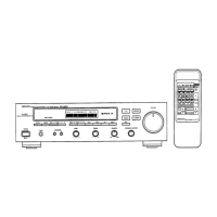
Provides overall unit specifications and details for the remote control.

Front Panel Overview

Front Panel Controls

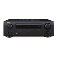
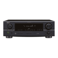
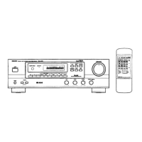
Identifies and describes the controls located on the front panel.

Display Indicators

Explains the various indicators present on the unit's display.

Rear Panel Overview

Rear Panel Connections

Details the connection terminals and ports on the rear panel.

Safety Information

General Warnings

Provides critical safety precautions for operating the equipment.

System Connections

Antenna Setup

Instructions for installing and connecting AM and FM antennas.

Input/Output Terminal Guide

Describes the function of each input and output terminal.

Connection Notes

Important notes and cautions regarding system connections.

Panel Control Functions

Front Panel Control Descriptions

Detailed explanation of each control and button on the front panel.

Tuning and Input Selection

Describes how to select radio bands, tune stations, and choose input sources.

Advanced Functions

Auto Preset and Memory Operations

Guides on using auto preset memory and manual station storage.

RDS and PTY Functionality

Explains the Radio Data System (RDS) and Programme Type (PTY) features.

Advanced Functions

Inputting RDS Characters

Instructions for inputting characters for station naming and RDS data.

RDS Search Modes

Details on using RDS, PTY, and TP search functions for station finding.

EON TA and Emergency Alarm

Explains Enhanced Other Network (EON) and Emergency Alarm functions.

Remote Control Usage

Battery Installation and Handling

Guidance on inserting, replacing, and handling remote control batteries.

Remote Control Operation Guide

Instructions for operating the receiver and other DENON components.

Troubleshooting

Reception Problems

Lists common issues with FM/AM reception and their solutions.

Audio Playback Issues

Addresses problems related to audio equipment playback and sound output.

Disassembly Instructions

Disassembling the Top Cover

Step-by-step guide to removing the top cover of the unit.

Disassembling the Front Panel

Procedure for removing the front panel assembly.

Disassembling the Rear Panel

Instructions for detaching the rear panel.

Adjustment Procedures

Idling Current Adjustment

Details the procedure for adjusting the idling current.

Measurement Setup Diagrams

FM Section Measurement Configuration

Diagram showing instrument connections for FM section measurements.

System Block Diagrams

Overall Block and Level Diagram

Illustrates the overall system architecture and signal flow.

Parts List Information

Parts List Conventions

Notes on interpreting part numbers, symbols, and specifications in the list.

Printed Wiring Board Parts

Main Unit Components (Semiconductors, Resistors)

List of semiconductor and resistor components for the main unit.

Main Unit Components (Capacitors)

List of capacitor components for the main unit.

Main Unit Components (Other)

List of miscellaneous components for the main unit.

Display Unit Parts List

Display Unit Components

List of semiconductor, capacitor, resistor, and other parts for the display unit.

Printed Wiring Board Patterns

Main Unit Wiring Patterns

Layout diagrams for the printed wiring patterns of the main unit.

Display and Tuner Unit Patterns

Wiring pattern layouts for the display and tuner units.

Exploded Views

Chassis and Cabinet Assembly View

Diagram showing the exploded view of the chassis and cabinet assembly.

Exploded Parts Lists

Main Unit Parts Breakdown

Detailed list of parts for the main unit assembly, including quantity.

Accessories and Hardware

List of included accessories, packing materials, and hardware.

Wiring Diagrams

System Wiring Overview Diagram

Diagram illustrating the overall wiring connections between unit modules.

Schematic Diagrams

Tuner, Display, and Main Unit Schematics

Detailed electronic circuit schematics for key unit modules.

Semiconductor Information

Integrated Circuit Details

Information and pinouts for various integrated circuits used in the unit.

Transistor and Diode Types

Details on transistors and diodes, including pin configurations and types.

Remote Control Sensor Details

SBX1610-52 Circuit Diagram

Circuit diagram and component information for the remote control sensor.

Related product manuals