


D
donaldthomasAug 12, 2025
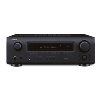
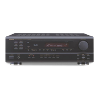
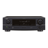
Why is there no sound from my Denon DRA-397 even though the display is on?
- AAaron BassAug 12, 2025
If your Denon Stereo Receiver's display is lit but no sound is coming out, several things could be the cause. First, check that the speaker cables are securely connected. Ensure the FUNCTION knob is in the correct position. Also, verify that the volume isn't set to the minimum. Finally, make sure that MUTING is switched off.