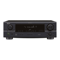
Hi-Fi AM-FM Stereo Receiver
SERVICE MANUAL
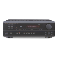
MODEL
DRA-295
AM-FM STEREO RECEIVER
SAFETY PRECAUTIONS .......................................... 36
SPECIFICATIONS ..................................................... 36
DISASSEMBLY ......................................................... 37
ADJUSTMENT...................................................... 38,39
BLOCK DIAGRAM ..................................................... 40
LEVEL DIAGRAM ...................................................... 41
SEMICONDUCTORS .......................................... 42~46
PRINTED WIRING BOARDS .............................. 47~51
NOTE FOR PARTS LIST........................................... 52
PARTS LIST OF P.W.B. UNIT ASS'Y ................. 53~59
EXPLODED VIEW ..................................................... 60
PARTS LIST OF EXPLODED VIEW .................... 61,62
PACKING VIEW ........................................................ 63
— TABLE OF CONTENTS —
Some illustrations using in this service manual are slightly different from the actual set.
PARTS LIST OF PACKING & ACCESSORIES ........ 63
WIRING DIAGRAM.................................................... 64
SCHEMATIC DIAGRAMS ................................... 65~69
(1/5) INPUT UNIT ........................................................... 65
VIDEO UNIT ........................................................... 65
(2/5) VOLUME UNIT ....................................................... 66
CONNECTOR UNIT ............................................... 66
(3/5) MAIN UNIT ............................................................. 67
(4/5) FRONT UNIT .......................................................... 68
SWITCH UNIT ........................................................ 68
POWER SW/HP UNIT............................................ 68
(5/5) TUNER UNIT .......................................................... 69
For U.S.A., Canada
& Europe model
14-14, AKASAKA 4-CHOME, MINATO-KU, TOKYO 107-8011 JAPAN
Telephone: 03 (3584) 8111
X0118 842 NC 0108