EasyManua.ls Logo

Denon DRA-275RD Service Manual

Denon DRA-275RD
36 pages
To Next Page IconTo Next Page
Page #1 background imageLoading...
Page #1 background image
D
FE
N
O
N
Hi-Fi
AM-FM
Stereo
Receiver
SERVICE
MANUAL
MODEL
DRA-3
75RD
MODEL
DRA-275RD/275R
AM-FM
STEREO
RECEIVER
DRA-275R
TABLE
OF
CONTENTS
OPERATING
INSTRUCTIONS
casio.
ceszissipcacredesp
sites
sas
anc
it
adiee
sl
ccmusablei
SUA
coh
aden
musta
tent
ectasaas
3
PIGASSE
NEE
serial
Lteepdectesl
oh
as
ti
cremate
anon
ae
elects
eure
esa
acne
beh
etan
Meal
tied
Stee
Nit
co
10
WIRE
ARANGEMEN
ES
cect.
200,
os
sersscepcyy
nance
sds
scutes
edasalghicwns
Gace
divieeia
cl
cadhsshedeuasletea
divans
poulesnousnitinebia@micie
1
METHOD
OF
ADJUSTMENT
..
ec
AZAS
BLOCK
VEVEL.
DIAGRAM
22.
Gaec
Sewvcan
dachinins
ucths
usnva
ins
CGeinalalasaiaiuied
saat.
tate
naiat
hea
teatoaslgstid
er
ayliebs
14
SEMICONDUCTORS
00.
.sssesssseesssseeeseeeeseee
me
.
15~20
PRINTED
WIRING
BOARD
PATTERNS
........-cscssssesssseecssssssesssssevsesssssssssvecessessssseneane
ws
24-23
MAIN
ONUT
<a
ceccciasieg
tases
ses
cua
saceanva
ccs
needs
viveleesas
cncuepegacsspiedoa,tustesns
eabensaadeaei@hevuns
devas
testa
niandensecsaetouta
Socata
tevavdtivaiieoaste
es
a1
DISPLAY
UNIT
..
a
1
22
TUNER
UNIT...
23
RIOT
FOR
PARTS
LIS
8
ct
raned
at
sccecteseata
leat
ts
ast
cecaeel
samen
accawin
te
wit
eivaasnas
Rtas
cacsniat
tnd
em
eake,
24
PRINTED
WIRING
BOARD
PATTERNS
.......ce0css0ss-e-:
25
=29
EXPLODED
VIEW
OF
CHASSIS
AND
CABINET
.........cccscssccscssscesssssssssessecesssessssecsssecssissssssesesssecesssisssesiesssvessssveesuesesesee
30
PARTS
LIST
OF
EXPLODED
VIEW...
eee
s0i3
Bl
WIRING
DIAGRAN..............
0c
eee
santa
Ss
tedsddvees
Stalder
cusibianeaaiear
Slaten
duatesteraes
32
SCHEMATIC
DIAGRAM
Ge.c0.)
cscscseceeesssiiuessesweddsea
cea
teavsesodeans
dienes
canetya
sietvened
bees
scaes
ced
dis
ea
hepswcaer
ovabcataasns
covtawestausnel
tine
33,
34
@
Some
illustration
using
in
this
service
manual
is
slightly
different
from
the
actual
set.
NIPPON
COLUMBIA
CO.
LTD.

Other manuals for Denon DRA-275RD

Question and Answer IconNeed help?

Do you have a question about the Denon DRA-275RD and is the answer not in the manual?

Denon DRA-275RD Specifications

General IconGeneral
BrandDenon
ModelDRA-275RD
CategoryStereo Receiver
LanguageEnglish

Summary

DENON Hi-Fi AM-FM Stereo Receiver

Service Manual Overview

Introduction to the service manual, identifying the product and document type.

Model Identification

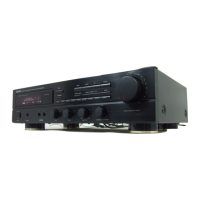
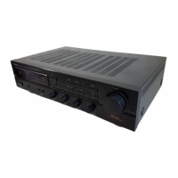
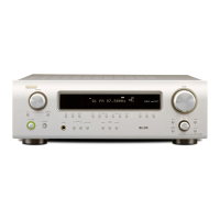
Specifies the Denon receiver models covered: DRA-375RD, DRA-275RD/275R.

SAFETY INSTRUCTIONS

General Safety Precautions

Covers essential safety guidelines for operating and servicing the equipment to prevent hazards.

Electrical Shock Warnings

Alerts users about the risks of electric shock and the need for qualified service personnel for repairs.

Notes on Usage and Installation

Installation Precautions

Provides guidelines for proper physical placement and ventilation of the receiver for optimal performance and safety.

Front Panel Controls and Indicators

Part Identification and Function

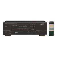
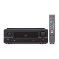
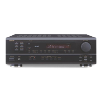
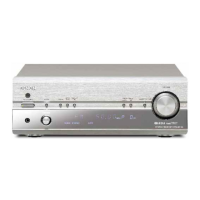
Details the function of each button, knob, jack, and display element on the receiver's front panel.

Rear Panel Connections

Terminal Identification and Connectivity

Explains the rear panel layout, input/output terminals, and their respective connection procedures.

Setup and Function Usage

Remote Control Operation

Remote Control Usage Guide

Instructions for using the RC-812 remote control unit, including battery installation and general usage.

Troubleshooting Guide

Problem Resolution

A guide to identify and resolve common operational issues encountered with the receiver.

Technical Specifications

Performance Specifications

Detailed technical data covering power output, frequency response, sensitivity, and other performance metrics.

Disassembly Procedures

Adjustment Methods

Idling Current Adjustment

Guide for measuring and adjusting the idling current for optimal audio performance.

Block/Level Diagram

System Signal Flow Diagram

Visual representation of the receiver's internal circuitry and signal flow between major functional blocks.

Semiconductor Details

Integrated Circuit Diagrams

Semiconductor Components

Remote Control and Display Information

Printed Wiring Board Layouts

Main Unit Parts List

Exploded View of Chassis and Cabinet

Chassis and Cabinet Assembly Diagram

An exploded view showing the physical assembly of the receiver's chassis and cabinet components.

Parts List for Exploded View

Wiring Diagram

SCHEMATIC DIAGRAM (1/2)

Circuit Details Part 1

First part of the detailed circuit schematic illustrating component interconnections and signal paths.

SCHEMATIC DIAGRAM (2/2)

Circuit Details Part 2

Second part of the detailed circuit schematic covering the remaining functional blocks of the receiver.

Related product manuals