EasyManua.ls Logo

Denon DRA-265R Service Manual

Denon DRA-265R
27 pages
To Next Page IconTo Next Page
Page #1 background imageLoading...
Page #1 background image
D
E
N
O
N
Hi-Fi
AM-FM
Stereo
Receiver
SERVICE
MANUAL
NRA-265R
AM-FM
Sienuv
RECEIVER
DENON
"0
00
commentssu.re
mana
notin
DFA-265R.
TABLE
OF
CONTENTS
OPERATING
INSTRUCTIONS
.....
0...
c
cee
ce
nee
teen
e
eee
en
ee
nner
e
nett
en
nee
2~7
DISASSEMBLY
\oj0:5cccieiesiic's
wide
arab
alaacecsveawie
ote
etaue
@
asd
Vda
2G
Fhe
gia
dace
See,
Seta
dhal
ole
ap
aTa
sede
ata
mace
dua.
8
METHOD
OF
ADJUSTMENTS
....
2...
eect
eee
ent
e
eee
e
eee
e
eee
t
teenies
9
CONNECTION
DIAGRAM
OF
MEASURING
INSTRUMENTS
.....
22...
c
cc
cee
cee
ence
eens
10
BLOCK/LEVEL
DIAGRAM
........-.-
0c ee
cee
eee
eee
Aint
staat
ea
Sie
an
ape
ee
ahaa
wtwann
Aad
ali
11
NOTE
FOR
PARTS
LIST
0
ficcsie
ceding
darn
cca
dea
aioe,
e
eee
tcie
Ne
ana
Tannese
aye
Sub
wale
ea
eM
a
eeealgtes
Dados
12
PRINTED
WIRING
BOARD
PARTS
LIST
....
0.
cece
cee
ect
e
eee
eee
eee
tenn
tenes
13~17
PRINTED
WAIRING
BOARD
PATTERNS
..........
0.2
c
cece
ccc
cee
eee
e
eee
eee
eens
18,
19
1U-2817
MAIN‘UNIT-ASSIV
os:
ccsid
dic
cenetc
tas
eat
oh
tine
Baws
Pe
ueeigitas
bala
De
a
ah
ereis
BALL qire
dts
18
10-2819
DISPLAY
UNIT
ASS'Y
ois
oe
eens
cds
ealge
eee
ea
cena
nae
wade
ee
swe
alee
amped
ete
19
1U-2818
TUNE
UNIT
ASS'Y
«oc
eect
eee
eae
Bitsy
magna
Bipsneatee
care
aaa
19
EXPLODED
VIEW
OF
CHASSIS
AND
CABINET.
......
0c
ec
ccc
cece
ee
ee
eee
eee
ene
eens
e
tees
20
PARTS
LIST-OF
EXPLODED
VIEW
2
cee
ice
i i
ew od
eo
ies
Oe
Neca
Ses
a
4
We
ea
ala
tiene
Qrete
GS
Aid
Oe
21
WIRING:DIAGRAM®
jsisfcecges
abn
tid
Se
cee
ee
highend
Sn
ne
ana
hb
be
wide
ow
gaan
eS
eaherealanl
08
be
Ved
dares
22
SCHEMATIC
DIAGRAM)
occ
occ
ae
ime
Fo
Seed
de
desea
had
de
Oe
dea
es
eae
bea
ae
me
23
SEMICONDUCTORS
34
citidid
teceterciise
Satine
Seana
din
aievere
eatin
soo
eceetva
Pe
cae
gretbndhs
aan
Wis
Shiela
ene
Vaetieme
24,
25
NIPPON
COLUMBIA
CO.
LTD.

Other manuals for Denon DRA-265R

Question and Answer IconNeed help?

Do you have a question about the Denon DRA-265R and is the answer not in the manual?

Denon DRA-265R Specifications

Amplifier Section IconAmplifier Section
continuous power output55 W + 55 W (4 ohms, 1 kHz)
total harmonic distortion0.03% (-3 dB at rated output, 8 ohms)
frequency responsePHONO RIAA Standard Curve 20 Hz ~ 20 kHz + 0.5 dB
Tuner Section IconTuner Section
receiving range [FM]87.5 ~ 108 MHz
usable sensitivity [FM]0.9 pV (10.3 dBf)
signal to noise ratio [FM MONO]82 dB
General Specifications IconGeneral Specifications
power supplyAC 230 V 50 Hz
power consumption104 W
dimensions434 mm (W) x 119 mm (H) x 306 mm (D)
Remote Control Unit IconRemote Control Unit
remote control systemInfrared pulse system
power supply3V DC Two size “AA” (R6) dry cell batteries
external dimensions60 mm (W) x 175 mm (H) x 18 mm (D)

Summary

Safety and Installation Precautions

Safety Warnings

Important warnings on electric shock, fire, and moisture.

Installation Guidelines

Instructions for proper unit placement and clearance.

Usage and Compliance

General Usage Notes

Key points for operating the receiver safely and effectively.

Included Accessories

Checklist of items supplied with the main unit.

Declaration of Conformity

Manufacturer Compliance Statement

Statement confirming adherence to technical regulations.

Connections and Wiring

Panel Terminal Connections

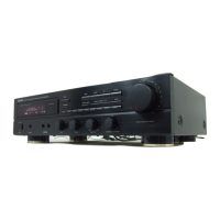
Diagrams and descriptions of all rear panel input/output terminals.

Speaker and Antenna Setup

Guidelines for connecting speakers and installing antennas.

Connection Best Practices

Important notes and precautions for making audio connections.

Control Panel and Functions

Front Panel Controls

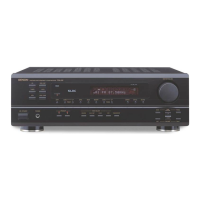
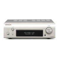
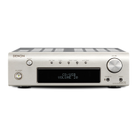
Detailed explanation of buttons, knobs, and their functions.

Display Indicators

Explanation of the meaning of various display indicators.

Receiver Operation

Station Presetting and Recall

How to store and retrieve radio stations using memory functions.

Station Name Input

Instructions for assigning custom names to radio stations.

Remote Control Operation

Remote Unit Overview

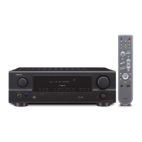
Introduction to the RC-174 remote control and its system capabilities.

Battery Installation

Steps for inserting and replacing batteries in the remote control.

Remote Operation Tips

Guidance and precautions for effective remote control usage.

Troubleshooting and Specifications

Problem Resolution Guide

Table to diagnose and resolve common receiver issues.

Technical Performance Data

Detailed specifications for amplifier, tuner, and general performance.

Component Specifications

Specifications for remote control and power unit.

Disassembly Procedures

Top Cover Removal

Steps to safely remove the top cover of the unit.

Panel Disassembly

Procedures for removing the front and rear panels.

Adjustment Procedures

Idling Current Calibration

Detailed steps for adjusting idling current using a voltmeter.

Measurement Diagrams

FM Section Test Setup

Diagram for connecting instruments for FM section adjustment.

Block and Level Diagrams

System Signal Flow

Overall block diagram showing signal paths and modules.

Signal Level Chart

Chart illustrating signal levels for various input types.

Parts List Information

Ordering and Part Notes

Guidance on part availability, ordering, and symbology.

Component Specifications

Details on resistor and capacitor types, codes, and units.

Printed Wiring Board Parts - Main Unit

Main Unit Semiconductors

List of semiconductor components for the main unit.

Main Unit Resistors

List of resistors on the main unit's printed wiring board.

Printed Wiring Board Parts - Main Unit (Cont.)

Main Unit Capacitors

List of capacitors on the main unit's printed wiring board.

Main Unit Other Parts

List of miscellaneous components on the main unit's PCB.

Printed Wiring Board Parts - Tuner Unit

Tuner Unit Semiconductors

List of semiconductor components for the tuner unit.

Tuner Unit Resistors

List of resistors on the tuner unit's printed wiring board.

Printed Wiring Board Parts - Tuner Unit (Cont.)

Tuner Unit Capacitors

List of capacitors on the tuner unit's printed wiring board.

Tuner Unit Other Parts

List of miscellaneous components on the tuner unit's PCB.

Printed Wiring Board Parts - Display Unit

Display Unit Semiconductors

List of semiconductor components for the display unit.

Display Unit Capacitors

List of capacitors on the display unit's printed wiring board.

Display Unit Resistors

List of resistors on the display unit's printed wiring board.

Display Unit Other Parts

List of miscellaneous components on the display unit's PCB.

Printed Wiring Board Patterns

Main Unit (1U-2817) Layouts

Layout diagrams for the main unit's printed wiring boards.

Printed Wiring Board Patterns (Cont.)

Display Unit (1U-2819) Layouts

Layout diagrams for the display unit's printed wiring boards.

Tuner Unit (1U-2818) Layouts

Layout diagrams for the tuner unit's printed wiring boards.

Exploded Views

Chassis and Cabinet Assembly

Exploded diagram of the unit's physical construction.

Parts List by Exploded View

Component Parts List

List of parts corresponding to the exploded view references.

Accessories and Hardware

List of included accessories, screws, and cables.

Wiring Diagram

Unit Interconnection Diagram

Diagram showing how major units are wired together.

Schematic Diagrams

Tuner Unit Schematic

Detailed electronic schematic for the tuner section.

Main Unit Schematic

Detailed electronic schematic for the main unit.

Display Unit Schematic

Detailed electronic schematic for the display unit.

Semiconductor Component Details

Integrated Circuit (IC) Information

Pinouts and function descriptions for key ICs.

Transistor and Diode Identification

Identification and diagrams for transistors and diodes.

Remote Sensor Circuit

SBX1610-52 Sensor Details

Circuit diagram and component information for the remote sensor.

Semiconductor Component Details (Cont.)

Additional IC Pinouts

Further pinout and function details for integrated circuits.

Additional Transistor/Diode Data

More identification and data for transistors and diodes.

Remote Sensor Circuit (Cont.)

SBX1610-52 Component Breakdown

Specific component breakdown for the remote sensor unit.

Related product manuals