EasyManua.ls Logo

Denon DRA-25 Service Manual

Denon DRA-25
21 pages
To Next Page IconTo Next Page
Page #1 background imageLoading...
Page #1 background image
D
F
N
O
N
Hi-Fi
AM-FM
Stereo
Receiver
MODEL
DRA=-25/25L
AM-FM
STEREO
RECEIVER
DRA-25L
CONTENTS
PRECAUTIONS
FOR
INSTALLATION
ADVICE
FOR
USE
SPECIFICATIONS
NAME
OF
EACH
PART
CONNECTION
ANTENNA
INSTALLATION
REMOVAL
OF
EACH
SECTION
METHOD
OF
ADJUSTMENTS
CONNECTION
DIAGRAM
OF
MEASURING
INSTRUMENTS
SEMICONDUCTORS
DRA25
BLOCK
DIAGRAM
PRINTED
WIRING
BOARD
PATTERNS
AND
PARTS
LIST
PRINTED
WIRING
BOARD
EXPLODED
VIEW
OF
CHASSIS
AND
CABINET
&
PARTS
LIST
EXPLODED
VIEW
OF
CHASSIS
AND
CABINET
WIRING
DIAGRAM
SCHEMATIC
DIAGRAM
NIPPON
COLUMBIA
Co.
LTD.
Question and Answer IconNeed help?

Do you have a question about the Denon DRA-25 and is the answer not in the manual?

Denon DRA-25 Specifications

General IconGeneral
BrandDenon
ModelDRA-25
CategoryStereo Receiver
LanguageEnglish

Summary

Precautions and Advice

Installation Precautions

Guidance on proper placement and environmental conditions for the receiver.

Usage Tips

Recommendations for safe and optimal operation of the receiver.

Technical Specifications

Amplifier Specifications

Details on power output, distortion, and frequency response for the amplifier section.

Tuner Specifications

Specifications for the FM and AM tuner sections, including sensitivity and selectivity.

Component Identification

Front Panel Controls and Displays

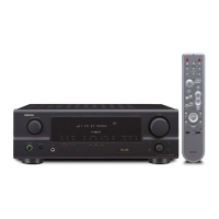
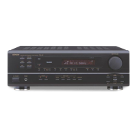
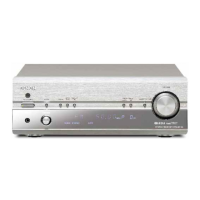
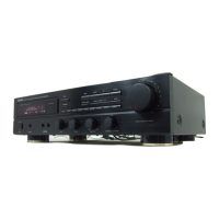
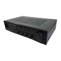
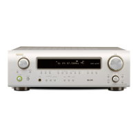
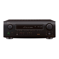
Identification of all buttons, knobs, and indicators on the front panel.

Back Panel Connections

Labeling of input/output terminals and power connections on the rear panel.

Connections and Installation

Audio and Speaker Connections

Guide for connecting external audio sources and speakers to the unit.

Antenna Installation Guide

Instructions for setting up FM and AM antennas for optimal reception.

Disassembly Procedures

Top Cover and Front Panel Removal

Steps for removing the outer casing and front panel assembly.

Internal Component Removal

Detailed instructions for detaching PCBs, inner panels, and heat pipe fins.

Measurement and Adjustment Procedures

Idle Current Adjustment

Procedure for measuring and adjusting the unit's idle current.

Measurement Setup Diagrams

Diagrams showing how to connect test equipment for FM and MW adjustments.

FM/MPX Alignment

MW Alignment

LW Alignment

Semiconductor Components (ICs)

Integrated Circuits (ICs)

List and diagrams of integrated circuits used in the receiver.

Semiconductor Components (Transistors)

Transistor Identification

Identification and pin configurations for transistors.

Semiconductor Components (Diodes)

Diode Identification

Identification and characteristics of diodes used in the unit.

System Block Diagram

DRA-25 Functional Overview

Diagram illustrating the functional blocks and signal flow of the DRA-25 receiver.

Printed Wiring Board Patterns

AMP Tuner Unit Parts List

List of components for the AMP Tuner Unit, including part numbers and remarks.

Tuner Control Unit Parts List

Tuner Control Unit Component Details

Component list for the Tuner Control Unit, detailing part numbers and quantities.

Printed Wiring Board Diagrams

Tuner Control Unit Layout

Visual layout of the printed wiring boards for the tuner control unit.

Exploded Views and Parts Lists

Chassis and Cabinet Parts List

Detailed parts list corresponding to the exploded views of the chassis and cabinet.

Exploded View Diagram

Receiver Assembly Diagram

Diagram showing the physical assembly of the receiver's chassis and cabinet components.

Wiring Diagram

Internal Wiring Connections

Schematic illustrating the internal wiring harness and connections within the unit.

Schematic Diagram (DRA-25)

DRA-25 Circuit Schematic

Detailed circuit schematic for the DRA-25 model, showing all components and connections.

Schematic Diagram (DRA-25L)

DRA-25L Circuit Schematic

Detailed circuit schematic for the DRA-25L model, showing all components and connections.

Related product manuals